background image

TECHNICAL SPECIFICATIONS 

Description 

7” Air 

Weight 

2.9kg/6.38lbs 

Spindle dia 

5/8” UNC 

Power requirements 

12cfm@90psi (3/8””BSP inlet) 

Maximum air pressure 

7 bar (100psi) 

No load RPM 

7,000 RPM 

Recommended hose bore - to a max length 10 metres 

10mm (3/8”)


Vibration (AEQ) 


Primary hand position (trigger position) 

6.2m/s

2

 (k) 

Test method in accordance with ISO standards BS EN ISO 28927-12:2012 


Noise 


Noise LpA (Pressure Level) 

90.0dB(A) 

Test methods in accordance with Pneurop test code PN8NTC1 & ISO 3744 


MAINTENANCE 

For  the  motor  make  sure  that  the  end 
plates that abut the cylinder are free from 
burrs  and  sharp  edges  and  if  necessary 
lap on a flat fine grade of abrasive paper.  
 
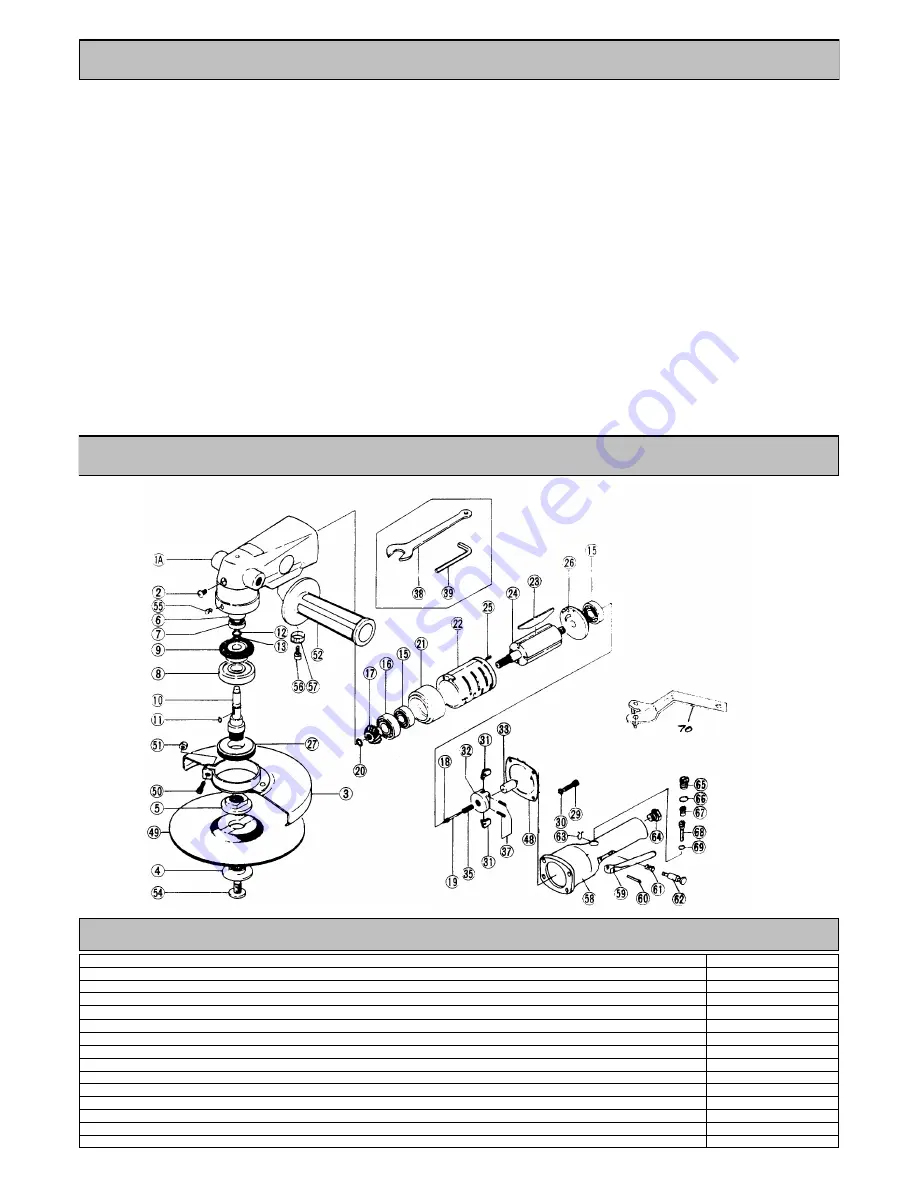
Press bearing (15) into rear case (26) and 
support the inner race of bearing (15) and 
press  the  non  splined  end  of  rotor  (24) 
into the assembly.  
 
Tap the rotor relative to the rear case and 
bearing  assembly  until  a  clearance  of 
approx.  0.0025”  (0.065mm)  is  achieved 
between the rotor and the rear case.  
 
Ensure  the  rotor  spins  freely  before 
assembling  the  rest  of  the  motor 
assembly. 
 

Reassembly 

Clean all parts and examine for wear. 
 
Use  only  distributor  or  manufacturer 
supplied spare parts. 
 
Particularly  examine  O-rings,  bearings 
and gears. 
 
Coat  all  parts  in  a  pneumatic  tool 
lubricating oil, one preferably containing a 
rust inhibitor. 
 
Grease  bearings  and  gears  with  a 
molybdenum  or  lithium  based  general 
purpose grease. 
 
Reassemble in the reverse order. 

This  machine  has  a  speed  controller  or 
governor, parts (21), (28), (42), (44), (45) 
and (46). 
The correct setting of this speed controller 
is  critical  to  the  safety  of  the  tool  and 
should  only  be  carried  out  by  a  trained 
competent person. 
 
The speed is set by assembling the speed 
controller,  measuring  the  output  spindle 
gear  shaft  (11)  speed  with  a  calibrated 
tachometer. 
 
Adjustment  to  the  spindle  speed  can  be 
made by rotating adjust screw (42). 
 
The speed of the grinder running free with 
an  air  inlet  pressure  of  100  psi  (7  bar) 
measured  at  air  inlet  (57)  must  not 
exceed 7,000 RPM. 

EXPLODED VIEW 

Summary of Contents for 735.7075

Page 1: ...OPERATION MAINTENANCE 7 ANGLE GRINDER ...

Page 2: ...e on daily basis and if tool starts to slow or lose power Pre Start Check Daily Check all bolts and screws for tightness Ensure that all fittings are secure Check condition of hub or drum assembly and replace flaps cutters or axles if required The air motor speed is preset at the factory to 7 000 rpm free running Always clear the air hose before connection to the machine Ensure that no moisture co...

Page 3: ... tool from air supply To dismantle insert the peg spanner 70 into disc nut 4 and with a spanner 38 on the flats of gear shaft 10 unscrew disc nut 4 take off disc 49 and unscrew disc receiver 5 Remove cover screw 50 and nut 51 and take off disc cover 3 Unscrew side handle 52 Grip the valve body 58 in a vice fitted with soft jaws and take out head screw 2 and screw 55 and with a suitable peg spanner...

Page 4: ...rox 0 0025 0 065mm is achieved between the rotor and the rear case Ensure the rotor spins freely before assembling the rest of the motor assembly Reassembly Clean all parts and examine for wear Use only distributor or manufacturer supplied spare parts Particularly examine O rings bearings and gears Coat all parts in a pneumatic tool lubricating oil one preferably containing a rust inhibitor Grease...

Page 5: ...peed rating 20 Check the speed of the grinder at least once per week if it is in regular use with an accurate tachometer 21 The tool must only be used with the grinding wheels as set out in section Use of the Tool and shown on parts list Never fit any other device 22 Carry out the instructions as set out in Putting into Service 23 Many countries have local or national rules re the use and fitting ...

Page 6: ...370 732344 Head screw 3 370 900305 Disc cover 4 370 900658 Disc nut Threaded 5 370 900657 Disc receiver Threaded 6 370 900308 Spacer 7 370 900309 Ball bearing 8 370 900310 Ball bearing 9 370 900311 Bevel gear 10 370 900656 Gear shaft Threaded 11 370 900313 Key 12 370 729290 Retaining ring 13 370 732919 Wave washer 15 370 1005478 Ball bearing 2 16 370 900314 Ball bearing 17 370 900315 Bevel pinion ...

Reviews: