SERVICING
Pre-Start Check (Daily)
Check all bolts and screws for tightness. Ensure that
all fittings are secure.
Check the drive belt for correct tightness. There
should be approximately 13mm (1/2") of free play
when the belt is depressed in the middle position
between the two pulleys. To check and set the belt
tension, refer to the
Belt installation & Adjustment
section.
Check condition of Cutter Drum Assembly and
replace components as required.
Check engine oil level. (Ensure that the engine is
level prior to carrying out this check). If the engine oil
level is low, refill with the relevant motor oil
recommended in
the engine
manufacturers
operating and maintenance manual.
Check that there is sufficient petrol in the fuel tank.
(Only refill when the engine is cold).
Air Models
; The air pressure regulator is preset at
the factory to 90psi with a blanking bleed plug fitted,
the air pressure regulators gauge will only show
approximately 40psi (2.75bar) when the machine is
in use, this is correct. Always clear the air hose
before connection to the machine. Ensure that no
moisture (condensation) is present in the air hose.
Check the security of all hoses clamps and fittings,
and that the air pressure is correct at 90psi (6.3bar).
Check that there is sufficient air tool oil in the
lubricator‟s reservoir. The air motor requires a
minimum of 180cfm of free air supply (not displaced,
as given by some compressor manufactures). In
particularly cold weather it is recommended that a
proprietary anti-freeze lubricating oil is used.
Electric Models
;
The TFP200 is supplied with a specially
commissioned electric motors and starter switch
assembly. Each unit is fully tested and the overload
relays have been calibrated and set according to the
manufactures specifications. In the event of
malfunction on a new machine, the owner should
first check that the power supply on site is suitable
and adequate. All cables should be fully uncoiled
and never left wrapped around cable reels or tied in
loops. The starter box is fitted with a safety feature to
protect the motor and relays from damage. The
starter boxes are preset and under no circumstances
should they be tampered with, stripped down or
adjusted, otherwise it will invalidate the warranty.
The starter control box lid must be unscrewed to
gain access to the Black reset button,
ensure that
the supply is disconnected prior to opening the
lid
.
110v Motor
Use a centre tap transformer with a continuous rated
output of
5.0KVA
and must be a 230v
20amp
supply.
Do not
add an extension lead to the transformer
input.
Do not
use a 230v 13amp domestic supply.
The motor requires the minimum of a 32amp, 110v
power supply.
To avoid voltage drop the machines extension cable
must also be 4.0mm
2
cross-section with a maximum
length of 20 meters or with 2.5mm
2
cross-section
extension cable a maximum length of 10meters.
240v and 415v Motors
Take particular care when using 240v or 415v
Machines, ensure that the electrical supply is
earthed and that breakers and fuses are correct for
the loading. The 240v motor requires the minimum of
a 13amp, 220v power supply. The 415v motor
requires the minimum of a 10amp, 380v power
supply. Always use the shortest possible length of
extension cable. To avoid voltage drop the cable
must be a minimum of 2.5mm. Maximum length of
cable 30 meters.
Starting Petrol Engines
1. Adjust the Handle Bar to a comfortable working
height.
2. Before starting work be sure that the Cutter Drum
is clear of the ground by turning the Hand Wheel anti
-clockwise to its full height, In this position the
machine‟s wheels are locked in position, acting as a
hand brake; the machine cannot then accidentally
roll away if left unattended.
3. Check that there is sufficient fuel in the fuel tank.
(See manufactures hand book for type)
4. Check that the engine oil level is correct. (See pre
-start check)
5. Open the engine fuel cock.
6. Set the throttle lever on the engine to quarter
open position.
7. For cold engine starting, move the carburettor‟s
choke lever to the choke "full on" position. (5.5hp
engine)
8. Check that the engine stop switch is in the "on"
position.
9. Pull the „Deadmans‟ handle towards the handle
bar and hold in position. (The motor will stop
immediately if this lever is released)
by turning the Hand Wheel anti-clockwise to its full
height, the machine‟s wheels are automatically
locked in position, acting as a hand brake; the
machine cannot then accidentally roll away if left
unattended.
3. Turn the tap on the air lubricator so that it is inline
with the lubricator, the air motor will then start to
rotate the drum.
4. Check in the sight glass that the lubricator is
supplying approximately one drop of oil every 30
seconds, this is
most important
to prevent the air
motor from seizing. This has been set high during
manufacture and will need adjusting on site. Check
that there is sufficient oil in the reservoir at regular
intervals. Be aware, the warranty does not cover a
seized or damaged motor due to lack of oil supply.
See separate lubricator sheet for instruction on filling
the air lubricator reservoir and for oil supply
adjustment.
Machine Operation
IMPORTANT
Do not pull the recoil starter cord to the end of is
travel as it may cause damage to the engine or
injury to the operator.
When the engine starts, recoil the cord slowly.
Do not allow the cord to snap back to its start
position.
10. Pull the recoil starter cord handle.
11. On the 5.5hp engine, after the engine starts,
open the choke approximately halfway, or until the
engine runs smoothly. Warm the engine up for at
least 3~4 minutes at the quarter open throttle setting.
Fully open the choke once the engine is sufficiently
warm, this will take longer during particularly cold
weather.
Starting Electric Motors
Inspect the supply cable; Check that no damage has
been caused to the outer casing and that there are
no exposed or loose wires. Obtain the assistance of
an electrician if a fault is found. Do not use the
machine until it has been rectified.
Check that the cable is not running across sharp or
jagged edges and that it is not in contact with any
liquid.
1. Adjust the Handle Bar to a comfortable working
height.
2. Before starting work be sure that the Cutter Drum
is clear of the ground by turning the
Hand Wheel anti-clockwise to its full height, In this
position the machine‟s wheels are locked in position,
acting as a hand brake; the machine cannot then
accidentally roll away if left unattended.
3. Pull the „Deadmans handle towards the handle
bar and hold in position.
(The motor will stop immediately if this lever is
released)
4. Press the green start button on the starter control
box and the motor will start.
Starting Air Motors
Check the security of all hoses clamps and fittings,
and that the supply air pressure is correct at (90psi
(6.2bar). Check that there is sufficient air tool oil in
the lubricator‟s reservoir.
Important:
See pre-start check before altering the
machine‟s pressure regulator.
1. Adjust the Handle Bar to a comfortable working
height.
2. Before starting work be sure that the Cutter Drum
is clear of the Ground.
ENGINE VERSIONS
CAUTION
Beware of
POISONOUS FUMES.
Start and
operate only in well-ventilated areas.
Be careful with
HOT COMPONENTS
.
Exhausts and other engine parts are hot during
and for some time after operation. Do not touch
them.
1. After starting the engine or motor, rotate the Hand
Wheel clockwise until the “Handbrake effect” is off
and the machine can move. Reduce the height until
the cutters make contact with the surface. It is
essential that the cutters are not lowered too far and
too hard onto the surface as damage could be
caused to the machine and cutter drum assembly.
Allow the cutters to “float” on the cutter shafts
without heavy downward pressure. As a guide
between half and one full clockwise turn on the hand
wheel should be sufficient. This floating action will
allow the cutters to perform as intended.
2. Complete a small area observing the
performance; reduce the throttle to tick over and on
both electric motor and engine powered machines,
release the Deadmans handle, inspect the finish
produced.
See
Cutter types & Applications
for advice on
cutter configurations.
3. Remember two light passes are quicker and more
cost effective that one slow heavy pass. Tests have
proved conclusively that heavy downward pressure
reduces cutter and drum life by over 50%.
4. Nuisance dust should be removed by connecting
an industrial vacuum cleaner (3000watts) to the
50mm port at the rear of the machine.
5. Alternatively on engine-powered machines, it is
acceptable to spray water on the surface being
worked or introduced via the vacuum port. The
Cutter Drum assembly life is increased by around
10% when operating the machine in this method.
Do not use the above method when using
electric machines due to the inherent danger of
the trailing cable becoming immersed in water.
NOTE:
Electrical motors and switches are not totally
waterproof; but are protected to IP44; take special
care to protect them from water to ensure safety
.
6. The TFP200 is normally used in a forward
motion; the rotation of the drum also helps with the
natural drive produced during it operation. The
operator can vary the speed of travel to determine
the final finish having already set the depth control.
Summary of Contents for TFP200
Page 1: ...TFP200 FLOOR PLANER OPERATION MAINTENANCE ...
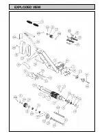
Page 6: ...EXPLODED VIEW ...
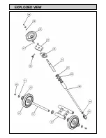
Page 7: ...EXPLODED VIEW ...


