SERVICING continued
It is permissible to operate the machine with a
backward and forwards action, each pass should be
overlapped to produce a uniform finish.
7. In emergency, when the cutter drum must be
lifted quickly from the work surface, it is not
necessary to turn the hand wheel, simply pull
backwards and downwards on the handlebar to lift
the front wheels and Cutter Drum off the floor, and
then release the Deadmans handle.
Shut Down
1. Turn the Hand Wheel clockwise to its full height,
until the machine‟s wheels are locked and act as a
brake.
Air Motors versions
, turn the tap on the lubricator
anti-clockwise until at right angles to the lubricator.
Electric versions
, release the Deadmans handle,
and disconnect from the supply.
2.
Petrol versions
, still holding the Deadmans
handle, move the engine‟s throttle lever to the slow
speed position and run the engine for 10 seconds.
(This avoids the engine from becoming washed
internally by neat fuel if switched off from high
engine revolutions.)
3. Release the Deadmans handle or switch off main
engine switch the engine will then stop.
4. Switch off the main engine switch.
5. Close the engine fuel cock.
:EMERGENCY SHUTDOWN:
Petrol and Electric Models: Release Deadmans
handle.
Air Motor: Turn off lubricator stop tap.
The clevis pin should be lubricated regularly with oil
to maintain a light, smooth height adjustment.
The toothed Drive Belt will give a long and trouble
free life if basic procedures are followed.
Daily check the drive pulleys for build up of deposits
and any trapped debris etc.
Check the belt and teeth for surface cuts and cracks,
as once the surface of the belt is damaged it will
soon fail.
Build up of dirt can cause two problems:
The belt can become over tightened through the
build up of dirt underneath the teeth and therefore
may no longer mesh correctly, all of the power is
then transmitted by the tip of the teeth with obvious
negative results.
Serious damage could result to the drive shaft,
bearings and drive motor if the belt is excessively
tight.
Generally when the motor is started and run a tight
belt can be detected by a low hum or whistle.
Warning
: Never operate the TFP200 without a belt
guard.
All fastenings should be checked daily for tightness
and the drive belt for tension.
Check the individual motor or engine manufactures
instructions for details on their service
recommendations.
Short period storage: up to 3months.
Clean outside of machine, inspect the Drum, flail
shafts and cutters for wear; replace any worn parts
as required.
Remove any build up of material from inside of the
Cutter Drum area.
Cover the machine to protect it: Store the machine in
a dry place.
Be sure to check security of all fastenings after any
lay up period.
See also engine manufactures operation and
maintenance instruction book.
Long period storage: over 3months
Clean outside of machine, inspect the Drum, flail
shafts and cutters for wear; replace any worn parts
as required.
Remove any build up of material from inside of
Cutter Drum area.
When engine is cold, remove the fuel from the fuel
tank and carburettor float chamber; see engine
manufactures operation and maintenance instruction
book for method.
Cover the machine to protect it: Store the machine in
a dry place.
After any long lay up period be sure to check
security of all fastenings, change engine oil as per
engine manufactures instructions and refill the tank
with fresh petrol.
See also engine manufactures operation and
maintenance instruction book.
Note: Always follow local regulations on the storage
of petrol and for the disposal of used engine oil.
IMPORTANT
Normal slack should be approximately 10~15mm
(1/2") when the belt is depressed on one side in
the middle position between the engine pulley
and drive pulley.
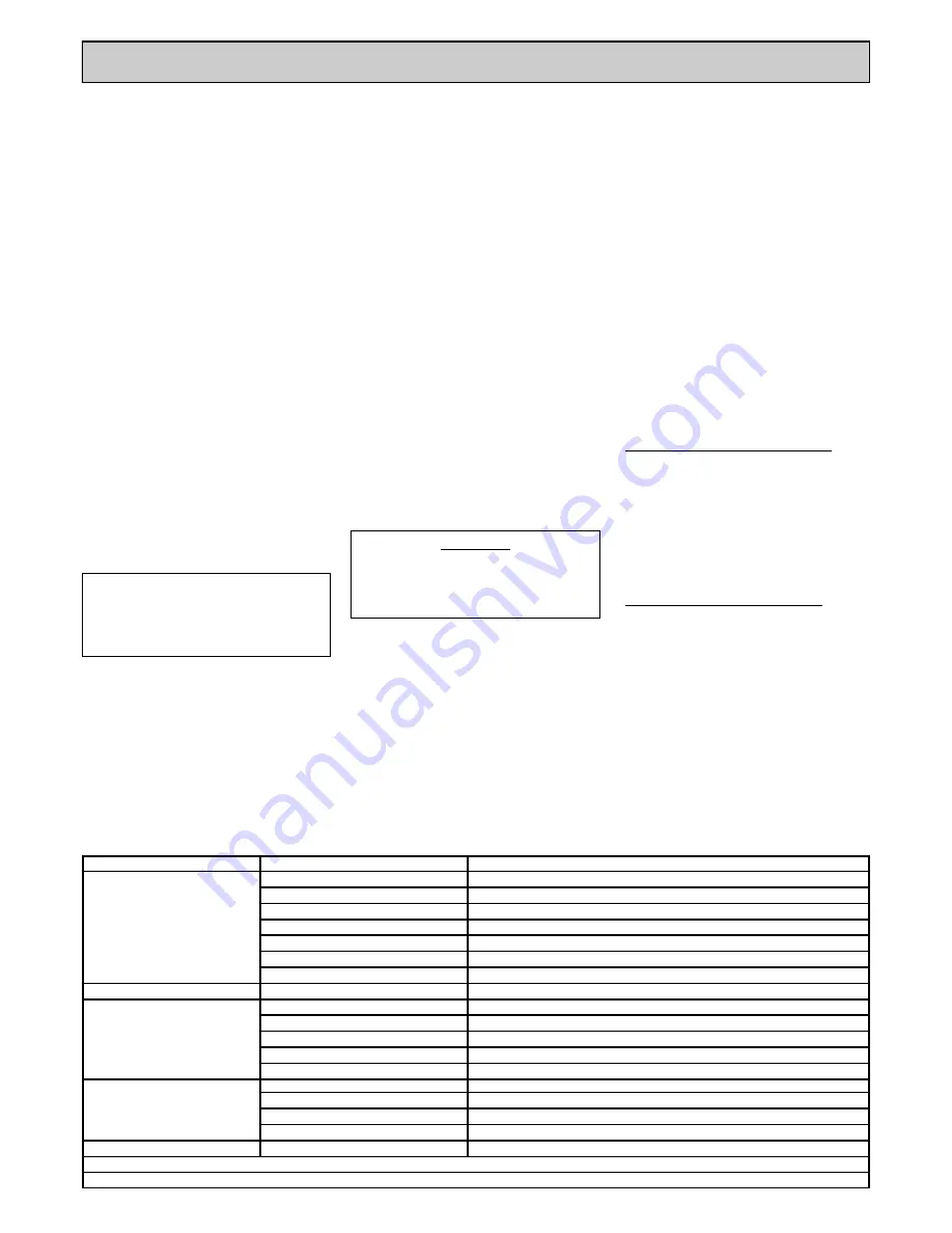
FAULT
CAUSE
ACTION
Engine stops suddenly or does not
run correctly
No fuel in the fuel tank.
Refuel fuel tank. (See safety section.)
Spark plug faulty.
Replace spark plug.
Fuel blockage.
Check fuel line and strainer.
Air cleaner blocked.
Replace air cleaner element.
Low oil level. (A low oil cut out is fitted)
Rectify leaks and replenish oil.
Electric motor stops suddenly
Blown electrical supply fuse.
Replace fuse.
Motor overload protection activated
Disconnect electricity supply at mains and reset button inside starter box.
Electric motor will not start
Deadmans handle not engaged
Pull Deadmans lever against handle bar and press start button.
Planer is slow or erratic
Drive Belt slack or failed.
Replace Belts or adjust tension.
Worn Drum Cutters
Replace Cutters.
Loose or a failed drive belt.
Replace Belts and adjust tension.
Surface too rough.
Use Trelawny TF260 surface Planer to increase production.
Low air supply or air pressure
Requires a minimum of 160cfm @ 90psi
Engine will not start
No fuel in the fuel tank.
Refuel fuel tank, see safety precautions.
Low oil level.
Rectify leaks, replenish oil.
Water in fuel/wrong fuel type
Drain fuel tank, float chamber, and refuel with correct fuel type.
Spark plug faulty.
Replace spark plug.
Engine will not turn over
Oil in Cylinder.
See section.
1 - Safety Precautions
.
Use above information in conjunction with the engine manufacturers Operation and Maintenance Manual.
If problem has not been cured by above actions, contact your local Trelawny agent or engine manufacturer for advice or rectification.
4. Slide the toothed belt off the engine pulley and
then remove the belt from the drive pulley. It may be
necessary to lift the left hand end (viewed from the
front of machine) of the engine/motor slightly to
facilitate removal and also during installation.
5. Place the new belt partially onto the drive pulley
first; locate the belt‟s teeth in the drive pulley‟s tooth
grooves.
6. Then slide the belt over the engine drive pulley,
slide the belt fully into position, and ensure that both
pulleys have the belt‟s teeth engaged in the grooves
and that the engine/motor pulley is positioned
directly above the drive pulley.
7. Adjust the tension of the belt by moving the
engine towards the front of the machine.
When the engine is in the correct position, (Normal
slack should be approximately 13mm (1/2")) lightly
tighten the engine retaining bolts and recheck the
belt tension.
The engine must also be parallel to the front of the
engine mounting plate otherwise the belt will not run
true.
Please bear in mind that the belt will also tighten
further as the engine mounting bolts are tightened.
Adjust the engine position until the correct belt
tension is achieved. Carefully rotate the drive pulley
by hand to ensure that the belt is running true.
8. Finally tighten all engine bolts, refit the belt guard
and tighten the belt guard-retaining
bolt.
Belt Installation &
Adjustment
1.
Ensure that all power or air to the machine is
switched off and disconnected.
2. Remove the belt guard by unscrewing the bolt in
the centre of the belt Guard.
3. Loosen the engine mounting plate bolts to allow
the engine to move along the chassis‟s engine
mounting bolt slots and on electric motors loosen
also the motor to slide mounting fixing bolts.
Maintenance & Machine
Storage
After use, clean the machine to remove all build up
of dust and surface residues. If using a hosepipe or
pressure washer take care not to direct water at
electrical components and switches.
Note: Motors and switches are not waterproof.
Ensure that the height adjustment thread is cleaned
and then lightly greased. Periodically it should be
completely removed and the female thread section
cleaned and greased. At the same time the self-
aligning bearing at the top of the shaft should be
greased using a grease gun.
Summary of Contents for TFP200
Page 1: ...TFP200 FLOOR PLANER OPERATION MAINTENANCE ...
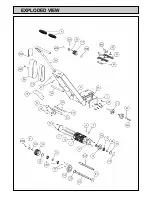
Page 6: ...EXPLODED VIEW ...
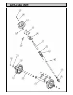
Page 7: ...EXPLODED VIEW ...


