BS/JIG
-11-
-11-
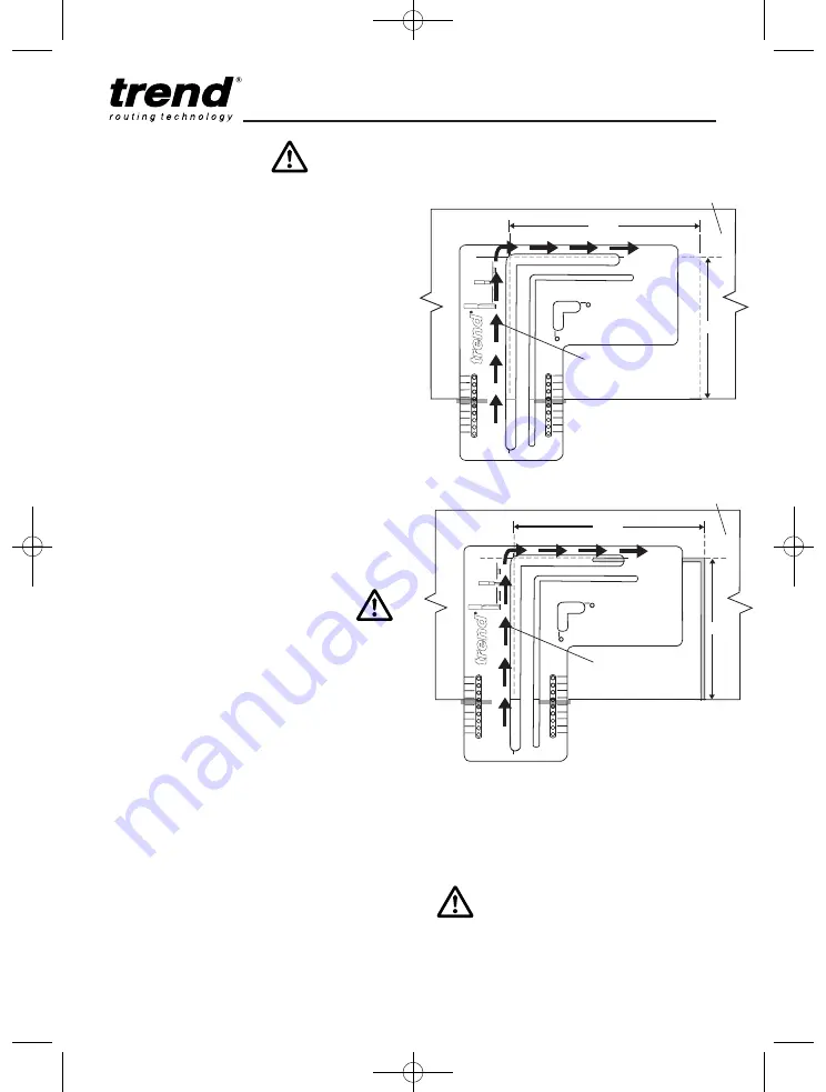
Routing the Worktop
I
With a 30mm guide bush and a 12.7mm
cutter fitted to the router, set the depth of cut
at approximately 8mm. Position the router in
the sink recess slot, switch on the router,
plunge down and rout the left half of the
recess. Cut in from the worktop edge,
travelling in a clockwise direction.
I
Increase the depth of cut and repeat until cut
is complete. At the end of each cut release
plunge and switch off router.
I
Remove the jig and then carefully turn the
worktop upside down.
I
To rout the second half of the recess, re-
position the jig as shown. Remember to re-
insert any packing piece that was used for
routing the first half. The sliding datum block
may be needed to line up.
I
Clamp the jig in place. Remove the sliding
datum block if used. Rout the remaining side,
again ensuring that the worktop is supported,
including the waste piece.
340
360
380
400
420
440
460
480
500
340
360
380
400
420
440
460
480
500
90°
517mm
Topside of worktop
r
outing
technology
30 mm
16 mm
12.7
mm
BS/JIG
For
Recess
For
W
ater
Drip Groove
R2.5 mm
405mm
Direction of
router travel
340
360
380
400
420
440
460
480
500
340
360
380
400
420
440
460
480
500
90°
517mm
Underside of worktop
r
outing
technology
30 mm
16 mm
12.7
mm
BS/JIG
For
Recess
For
W
ater
Drip Groove
R2.5 mm
405mm
Direction of
router travel
Routing the Water Drip Channel
I
A water drip channel can be routed to the
underside of the worktop to allow water to
drain off.
I
Fit a 16mm guide bush and a R2.5mm radius
cutter to the router.
I
With the worktop surface faced downwards,
line the inner edge of the jig’s drip channel
groove with the recess edge and clamp in
place. This will give a drip channel about
5mm back from the recess.
I
Set the router cutter to plunge about 5mm
into the worktop. Ensure the 16mm guide
bush is placed in the drip channel slot. Start
the groove 5mm from the worktop front edge
and rout in a clockwise direction.
I
After the first half has been routed,
re-position the jig for the second half
and repeat the operation.
I
Stop the groove 5mm before the worktop
front edge.
1st Half
2nd Half
Ensure the drip groove starts 5mm in
from the worktop front.
MANU/BS v1 25/3/11 16:33 Page 11


