background image


© Copyright 2017 TRENDnet. All Rights Reserved. 


TRENDnet User’s Guide


TEW-740APBO / TEW-740APBO2K 

55


Multiple Language 

System > Authentication > VLAN # > Multiple Language 

This section allows you to create additional languages when using the multiple language 
option for the built-in captive portal login page template. 
 

1. Log into your access point management page (see “

Access your access point 

management page

” on page 28). 


2. Click System, click on Authentication, and in the first entry VLAN 0, in the Action 

column, and click on drop-down list and click Multiple Language. Review the settings 
and click Save to apply the changes.  


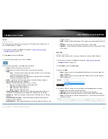
Create New Language – By default, English has already been added to the list. To 
create a new language, click this option and enter in the text strings for the new 
language. The preview window will display the current  built-in login page 
template. 


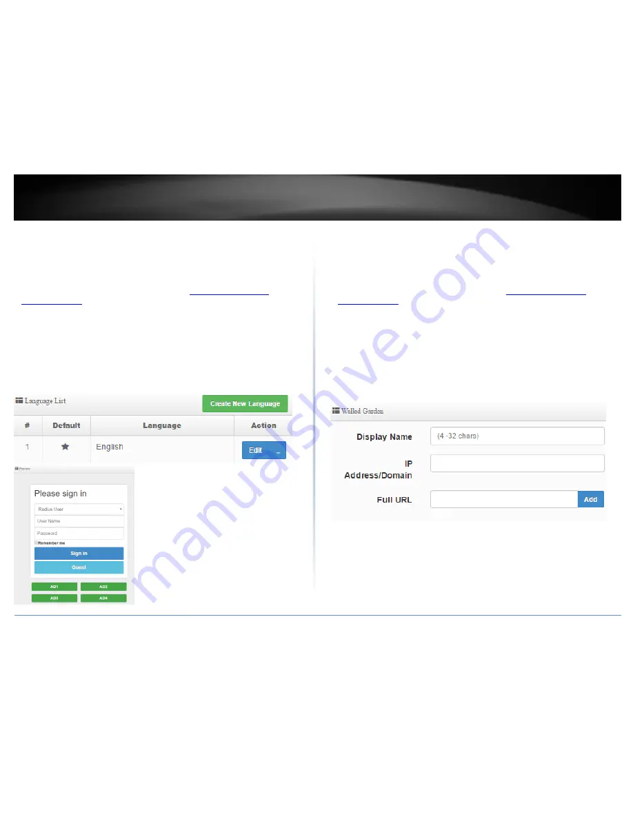
Walled Garden 

System > Authentication > VLAN # > Walled Garden 

This section can allow you to provide content such as advertisement web pages for 
users to access the websites listed before login and authentication. 
 

1. Log into your access point management page (see “

Access your access point 

management page

” on page 28). 


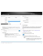
2. Click System, click on Authentication, and in the first entry VLAN 0, in the Action 

column, and click on drop-down list and click Walled Garden. Review the settings and 
click Add to add the entry to the walled garden list and click Save to apply the 
changes.  


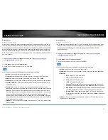
Display Name – Enter display name to easily identify the wall garden entry. 


IP Address/Domain: Enter the IP address or domain/URL of the website to add to 
the walled garden. 


Full URL: Enter the full URL or website name. 


Summary of Contents for TEW-740APBO

Page 1: ...TRENDnet User s Guide Cover Page ...

Page 2: ...Application Modes 24 AP Mode Access Point Mode 24 WDS Mode Pure WDS 25 Client Bridge AP Mode 26 WISP CPE AP Mode 26 Router Mode 27 CAP Control AP Mode 27 Access your access point management page 28 AP Management Settings 29 Management Setup 29 Set the device date and time 30 SNMP Settings 31 SNMP v2c 31 SNMP v3 32 SNMP Trap 32 Backup and restore your AP configuration settings 33 Backup configurati...

Page 3: ...s network 58 Configure your wireless network settings WLAN 58 WISP CPE AP Mode 59 Set the device LAN IP address settings 59 Configure the LAN DHCP Server 59 DHCP Reservation Static Lease 60 Configure WAN connection settings for WISP 61 Connect to your WISP Wireless Internet Service Provider 61 DMZ Demilitarized Zone 62 IP Filter 63 MAC Filter 63 Virtual Server 64 Access Control 64 Time Policy Sche...

Page 4: ...el TEW 740APBO provides wireless N300 point to point connectivity A variety of installation scenarios are facilitated with Access Point AP Wireless Distribution System WDS Client Bridge AP Wireless ISP WISP AP CPE AP and control AP CAP modes The IPX6 rated housing comes with wall and pole mounting hardware Wireless Modes Supports Access Point AP Wireless Distribution System WDS Client Bridge AP Wi...

Page 5: ...wireless coverage may vary depending on the wireless device s output power antenna gain antenna alignment receiving sensitivity and radio interference Additionally environmental factors such as weather conditions physical obstacles and other considerations may affect performance For optimal results we recommended consulting a professional installer for site survey safety precautions and proper ins...

Page 6: ... LED When the LED is on this indicates an active network connection to the LAN2 port If the LED is off there is no active network connection to the LAN2 port When the LED is blinking this indicates data is being transmitted or received on the LAN2 port Power PWR LED When the LED is on this will indicate that the device is receiving power and off if the device is not receiving power Reset Button Th...

Page 7: ...1 PoE port to supply power to the device Please note that the RJ 45 Ethernet cable between the proprietary PoE injector and the LAN1 PoE port of the access points supports a maximum length of up to 60 m 197 ft RJ 45 Ethernet cables longer than the maximum length specified may result in insufficient power to the device intermittent connectivity power loss and unstable physical link o 10 100 DATA IN...

Page 8: ...mary application of point to point wireless connectivity in WDS Wireless Distribution System Bridge Mode using AES encryption for security Minimum Installation Requirements Computer with RJ 45 Ethernet port and web browser 4 x RJ 45 Ethernet cables not included Phillips screwdriver not included for grounding wire installation only Additional TRENDnet TEW 740APBO H W v2 XR N300 directional wireless...

Page 9: ...gured to establish a WDS bridged connection to each using a unique AES encryption key For convenience a unique predefined administrator password is also assigned The predefined AES encryption key and administrator password can be found on the included wireless settings sticker or on the device label Important Note Purchasing this model does not require any additional configuration to establish the...

Page 10: ... On the device label located inside write down the WiFi MAC of each access point Note In this installation procedure example we will assume the WiFi MAC addresses TEW 740APBO 1 TEW 740APBO 2 WiFi MAC Address 00 11 22 33 44 00 00 11 22 33 44 11 Router Settings Router Default Gateway IP Address 192 168 10 1 Subnet Mask 255 255 255 0 In this installation procedure example we will configure the TEW 74...

Page 11: ...e on the far left then through the opening that was created in the previous step 3 Connect the other end of the RJ 45 network cable to the P DATA OUT port on the included PoE injector 4 Using another RJ 45 network cable connect one end of the 10 100 DATA IN port on the included PoE injector 5 Connect the other end of the RJ 45 network cable to your computer s Ethernet port 6 Connect the included p...

Page 12: ...ubnet mask of 255 255 255 0 Note For information on how to statically assign your IP address see the Appendix section 10 Open your web browser and type in the default IP address of the access point in the address bar then press Enter The default IP address is 192 168 10 100 11 When prompted login to the access point management page using the default user name and password settings User Name admin ...

Page 13: ...ing in the new password in the fields provided and then click the Save button at the bottom of the page 14 Click on the System tab and click on Mode Setup 15 Click on the Mode field and in the drop down list click on WDS Mode then click on Save Reboot When prompted to change the mode click Yes and wait for the device to apply changes and reboot Note After the device reboots you may need to login t...

Page 14: ...IP Setup section enter the IP Address 192 168 10 50 then click Save In the menu located at the top you will be prompted to reboot the device Click the Reboot button and in the following page click Reboot When prompted to reboot click Yes apply changes and reboot Note After the device reboots you will need to reconnect to the access point configuration page using the new IP address setting and logi...

Page 15: ...40APBO 2 the WDS passphrase must be the same passphrase configured on TEW 740APBO 1 21 Under WDS Client Setup check the first entry and enter the WiFi MAC address of TEW 740APBO 2 00 11 22 33 44 11 Then click Save In the menu located at the top you will be prompted to reboot the device Click the Reboot button and in the following page click Reboot When prompted to reboot click Yes apply changes an...

Page 16: ...pply changes and reboot Note After the device reboots you will need to reconnect to the access point configuration page using the new IP address setting and login 20 Click Enabled for the WDS Setup and under Authentication select AES Enter a WDS Passphrase 8 63 alphanumeric characters Note When configuring TEW 740APBO 2 the WDS passphrase must be the same passphrase configured on TEW 740APBO 1 21 ...

Page 17: ...the TEW 740APBO 2 access point management page click on Utility and click on Network Utility 4 In the IP Domain field enter the IP address 192 168 10 50 Next to Times click Ping Ping replies and 0 packet loss will indicate a successful WDS point to point bridge has been established between the two access points as shown below You can also check under Wireless and WDS Status the status of the wirel...

Page 18: ...the opening for the ground cable to be routed through Note The ground wire may need to be cut and extended using additional ground wire in order to reach a proper ground point 2 Reinstall the cover by lining up the guides into the notches as shown and push the cover down until the cover clips in and is secured 3 Insert the included fasteners through the holes located at the back of the access poin...

Page 19: ... Copyright 2017 TRENDnet All Rights Reserved 16 TRENDnet User s Guide TEW 740APBO TEW 740APBO2K Completed Installation Reference ...

Page 20: ... can find the preconfigured access point settings on the wireless sticker or on the device label beneath the cover where the Ethernet ports and LEDs are located No additional configuration is required Ma On the device label located inside you can also find the preconfigured default settings of each access point The TEW 740APBO access points will be preconfigured with the following settings TEW 740...

Page 21: ...picture below and sliding the cover in the two locations noted away from the access point 2 Remove the tab on the far left by gently bending it back and forth until the tab is removed This will create the opening the RJ 45 network cable to be routed through 3 Using a RJ 45 network cable connect one end of the cable to the LAN PoE port and push the cable into the guide on the far left then through ...

Page 22: ...er into a power outlet 7 Confirm the device is powered on through the PWR LED indicator Note Repeat steps 1 7 to power on and connect the second access point 8 Assign a static IP address to your computer s network adapter in the subnet of 192 168 10 x e g 192 168 10 10 and subnet mask of 255 255 255 0 9 Using another network cable connect one end to the 10 100 DATA IN port on the included PoE inje...

Page 23: ...Command Prompt application and in Mac you can use the Terminal application to run the commands for connectivity testing ping 192 168 10 50 Press Enter and wait for result ping 192 168 10 51 Press Enter and wait for result A successful connectivity test will appear similar to the result below for each access point Ping replies and 0 packet loss will indicate a successful point to point bridge conne...

Page 24: ...the opening for the ground cable to be routed through Note The ground wire may need to be cut and extended using additional ground wire in order to reach a proper ground point 2 Reinstall the cover by lining up the guides into the notches as shown and push the cover down until the cover clips in and is secured 3 Insert the included fasteners through the holes located at the back of the access poin...

Page 25: ... Copyright 2017 TRENDnet All Rights Reserved 22 TRENDnet User s Guide TEW 740APBO TEW 740APBO2K Completed Installation Reference ...

Page 26: ... signal passes through less dense material such as dry wall Dense materials like metal solid wood glass or even furniture may block or degrade the signal 4 Antenna orientation can also have a large impact on your wireless signal Use the wireless adapter s site survey tool to determine the best antenna orientation for your wireless devices 5 Interference from devices that produce RF radio frequency...

Page 27: ...ter Mode and CAP Control AP Mode The different modes can be found under System Mode Setup in the access point web management page AP Mode Access Point Mode An access point can be either a main relay or remote base station A main base station is typically connected to a wired network via the Ethernet port A relay base station relays data between main base stations and relay stations or remote base ...

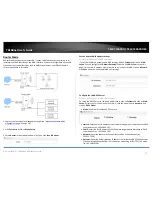
Page 28: ...pplication mode for the TEW 740ABPO and TEW 740APBO2K The built in high gain directional antenna makes this access point an ideal solution for establishing a single WDS point to point wireless bridge or link between two physical locations that are a great distance from one another Example 1 Point to Point Example 2 Point to Multi Point ...

Page 29: ...clients to connect The wired ports LAN1 PoE and LAN2 are logically bridged to the wireless interface The wired clients of access point are in the same subnet from Main Base Station and it accepts wireless connections from client devices WISP CPE AP Mode It can be used as an Outdoor Customer Premised Equipment CPE to receive wireless signal over the last mile helping WISPs deliver wireless broadban...

Page 30: ...rver functions CAP Control AP Mode CAP mode functions in AP mode but in addition this mode allows you to manage monitor and control other APs using the same firmware software You can configure multiple settings for multiple APs at the same time push out batch firmware upgrades from one convenient GUI interface The CAP Mode AP can discover and manage any CAP mode compatible APs on any of interfaces...

Page 31: ...he same subnet as the as the access point in order to access the access point management page Also make sure your access point is powered on through the included PoE injector and your computer is connected to the 10 100 DATA IN port on injector or connect to LAN2 Ethernet port Ex Access Point IP address changed to 192 168 0 100 255 255 255 0 example computer address 192 168 0 25 255 255 255 0 1 Op...

Page 32: ...or Password New Check Admin Password To change the default administrator password enter the new password in the field provide and again in the check field to confirm the password change Login Methods HTTP The standard unsecured web GUI method is enabled by default Check the box to enable or disable management access to the device via http web GUI access You can also check the default port used for...

Page 33: ...your access point management page see Access your access point management page on page 28 2 Click System and click on Time Review the settings and click Save to apply the changes Local Time Displays the current device date and time Mode NTP Server The device will obtain the date and time information automatically from an external NTP server Please note that the default gateway IP address and DNS m...

Page 34: ...c 1 Log into your access point management page see Access your access point management page on page 28 2 Click System and click on SNMP Review the settings and click Save to apply the changes Active Enable or disable SNMP version 2c RO Community Enter the read only community name RW Community Enter the ready write community name ...

Page 35: ...rd RW Username Enter the read write user name RW Password Enter the read write password SNMP Trap 1 Log into your access point management page see Access your access point management page on page 28 2 Click System and click on SNMP Review the settings and click Save to apply the changes Active Enable or disable SNMP Trap Community Enter the community name for SNMP trap IP 1 Enter the IP address of...

Page 36: ...K 6 Wait for the device restore settings Reset your AP to factory defaults Utility Profile Setting You may want to reset your device to factory defaults if you are encountering difficulties and have attempted all other troubleshooting Before you reset to defaults if possible you should backup your router configuration first If you are using are resetting an AP from the TEW 740APBO2K Bridge Kit the...

Page 37: ...sable sleep mode on your computer as this may interrupt the firmware upgrade process Do not upgrade the firmware using a wireless connection only using a wired network connection Any interruptions during the firmware upgrade process may permanently damage your router 3 Log into your access point management page see Access your access point management page on page 28 4 Click Utility and click on Sy...

Page 38: ...Status Overview This page will display the AP system summary information such as the currently operating mode system time firmware version MAC and IP address settings WiFi information 1 Log into your access point management page see Access your access point management page on page 28 2 Click Status and click on Overview ...

Page 39: ...e better signal and connectivity of the client device View currently connected authenticated users Status Online Users Only when using the guest or user authentication feature this page will display information about the currently connected authenticated users 1 Log into your access point management page see Access your access point management page on page 28 2 Click Status and click on Online Use...

Page 40: ... wireless connectivity to an existing wired network Set the device to AP mode System Mode Setup 1 Log into your access point management page see Access your access point management page on page 28 2 Click System and click on Mode Setup 3 Select Access Point AP Mode in the mode drop down list Then click Save Reboot Set the device LAN IP address System VLAN Setup By default the primary LAN interface...

Page 41: ...anning Tree Enable this setting only if you are using redundant wired and wireless bridged links WDS to prevent loops and multiple paths Example below with redundant WDS bridge link between 3 access points Control Port Used CAP Mode Only Enable this setting to allow management access from another TEW 740ABPO AP running in CAP Control AP mode This will allow the management AP to push settings the c...

Page 42: ...A2 wireless security requiring a specifically assigned passphrase to connect to the wireless network Passphrase 8 63 alphanumeric characters o WPA WPA2 Enterprise Applies standard WPA or WPA2 wireless security requiring the use of the third party RADIUS authentication server to authenticate wireless clients connecting to the wireless network The third party RADIUS authentication server is external...

Page 43: ...P service Start IP Enter the first IP address of the IP address range pool to distribute to DHCP client devices ex 192 168 10 101 End IP Enter the last IP address of the IP address range pool to distribute to DHCP client devices ex 192 168 10 199 Netmask Enter the subnet mask to distribute to DHCP client devices ex 255 255 255 0 Gateway Enter the default gateway IP address to distribute to DHCP cl...

Page 44: ...page on page 28 2 Click System and click on VLAN Setup 3 For the first entry in the list VLAN 0 under the Action column click the arrow next to the Network button and select DHCP Server In the Static Lease IP Setup section please review the settings below and click Save when completing the changes Comment Add a comment or name to help easily identify the device or purpose of the DHCP static IP lea...

Page 45: ...8 2 Click System and click on VLAN Setup 3 For the first entry in the list VLAN 0 under the Action column click the arrow next to the Network button and select 802 11r Fast Roaming In the Static Lease IP Setup section please review the settings below and click Save when completing the changes Fast Roaming Enable or Disable the fast roaming features Mobility Domain The identifier used to indicate a...

Page 46: ... Enter the Shared Identifier 128 bit Key Enter the 128 bit key 26 hexadecimal characters Hex Format 0 9 and A F Additional Wireless Settings Wireless Radio 0 Basic Setup 1 Log into your access point management page see Access your access point management page on page 28 2 Click Wireless and click on Radio 0 Basic Setup 3 Review the settings click Save when finished MAC Address Displays the WiFi MA...

Page 47: ...n 802 11b g request an Acknowledgement ACK send by receiving radio The transmitter will resend the original packet if correspondent ACK failed to arrive within specific time interval also refer to as ACK Timeout ACK Timeout is adjustable due to the fact that distance between two radio links may vary in different deployment ACK Timeout makes significant influence in performance of long distance rad...

Page 48: ...ick Save when finished Beacon Interval Beacon Interval is in the range of 20 1024 and set in unit of millisecond The default value is 100 msec Access Point AP in IEEE 802 11 will send out a special approximated 50 byte frame called Beacon Beacon is broadcast to all the stations provides the basic information of AP such as SSID channel encryption keys signal strength time stamp support data rate Al...

Page 49: ...ons due to hidden wireless clients RTS in AP will be enabled automatically if the packet size is larger than the Threshold value By default RTS is disabled in a normal environment supports non jumbo frames Short Preamble By default it s Enable To Disable is to use Long 128 bit Preamble Synchronization field The preamble is used to signal here is a train of data coming to the receiver The short pre...

Page 50: ...nds of a range from which the initial random back off wait time is determined o CWmax Maximum Contention Window The value specified here in the Maximum Contention Window is the upper limit in milliseconds for the doubling of the random back off value This doubling continues until either the data frame is sent or the Maximum Contention Window size is reached Once the Maximum Contention Window size ...

Page 51: ...wed is reached Valid values for the cwmax are 1 3 7 15 31 63 127 255 511 or 1024 The value for cwmax must be higher than the value for cwmin o Txop Transmission Opportunity is an interval of time when a WME AP has the right to initiate transmissions onto the wireless medium WM This value specifies in milliseconds the Transmission Opportunity Txop for AP that is the interval of time when the WMM AP...

Page 52: ...es in the table to establish the wireless WDS link MAC Address Displays the currently managed access point wireless MAC address or BSSID VLAN Setup Allows you to configure VLANs that will communicate across the wireless WDS link See the example diagrams below WDS Status Displays information about currently established wireless WDS links to the managed access point ...

Page 53: ...n column and click on Authentication Review the settings and click Save to apply the changes Authentication Enable or disable the authentication function on the interface Multiple Login Check the option to allow multiple logins concurrently with the same user Login Timeout Enter the idle timeout period before automatically logging out users in minutes Redirect URL Enter the URL of the web page to ...

Page 54: ...eck the option and enter the accounting port Typically the default RADIUS server account port is 1813 Authentication Select the authentication type used by your RADIUS server for user authentication Typically CHAP is used since it is more secure than PAP Secret Key Enter the shared secret required by your RADIUS server If you have bandwidth restriction limits for your guest users you can specify t...

Page 55: ...g their passwords Additionally these providers may allow for methods of creating a custom walled garden splash page By default Google and Facebook provider entries have already been created but you may add more providers to the list Assuming you have the developer API account and splash page already set up with your provider 1 Log into your access point management page see Access your access point...

Page 56: ...he settings and click Save to apply the changes Service Enable or disable POP3 Display Name Enter the name displayed for the POP3 user Host Enter the server domain or IP address Port Enter the port used for incoming POP3 traffic Default for POP3 is port 110 Connect Type Click the drop down and select the connection type used for POP3 incoming services none STARTTLS or SSL TTL POP3 Server Test Emai...

Page 57: ... preview area will display a preview of the built in login page Disabling the template option will allow you to enter in your own code for customization o Style Select one the predefined color schemes for the built in page template o Body Background Enter the HTML color code for the built in login page background o Content Background Enter the HTML color code for the built in login page content ar...

Page 58: ...ck this option and enter in the text strings for the new language The preview window will display the current built in login page template Walled Garden System Authentication VLAN Walled Garden This section can allow you to provide content such as advertisement web pages for users to access the websites listed before login and authentication 1 Log into your access point management page see Access ...

Page 59: ...ss of the privileged host device Backup Restore Authentication Profile Customized Pages System Authentication VLAN Profile This section can allow you to backup restore the authentication profile to your local drive and also backup store customized captive portal pages 1 Log into your access point management page see Access your access point management page on page 28 2 Click System click on Authen...

Page 60: ...ridge mode the device can function as an AP and create another wireless network to also bridge over it s connection from the wireless AP or router Set the device to Client Bridge AP mode System Mode Setup 1 Log into your access point management page see Access your access point management page on page 28 2 Click System and click on Mode Setup 3 Select Client Bridge AP Mode in the mode drop down li...

Page 61: ...e selected wireless network If security is enabled on the wireless network enter the WPA WPA2 PassPhrase or WEP key in the field provided Scroll to the bottom of the page and click Save when you have completed your settings and click Reboot in the top right menu to reboot the device and commit the changes Configure your wireless network settings WLAN Wireless AP Setup Verify you have established w...

Page 62: ...Access your access point management page on page 28 2 Click System and click on Mode Setup 3 Select WISP CPE AP Mode in the mode drop down list Then click Save Reboot Set the device LAN IP address settings System LAN Setup To set the IP address gateway and DNS settings click on System and click on LAN Setup Click Save when you have completed your settings Configure the LAN DHCP Server System DHCP ...

Page 63: ... by the DHCP service before expiration Upon expiration DHCP client devices will initiate new requests for DHCP client settings After the DHCP server settings have been configured and changes have been applied dynamic DHCP client leases will appear in the DHCP Client List table DHCP Reservation Static Lease System DHCP Setup Comment Add a comment or name to help easily identify the device or purpos...

Page 64: ...E Point to Point Protocol over Ethernet Your WISP requires a specifically assigned user name and password for authentication in order to establish connectivity PPTP Point to Point Tunneling Procotol Your WISP requires a specifically assigned user name and password for authentication in order to establish connectivity similar to PPPoE but a different type of tunneling technology Connect to your WIS...

Page 65: ...t is strongly recommended to use Virtual Server to allow access to your computers or network devices from the Internet Note Make the computer or network device for which you are establishing a DMZ link has a static IP address or static DHCP Lease 1 Log into your access point management page see Access your access point management page on page 28 2 Click Advance and click on DMZ 3 Review the settin...

Page 66: ...IDR ex 192 168 10 15 32 specifies only IP address 192 168 10 15 Any 0 0 0 0 0 Source Port Enter the source port number to apply the filter ex Port Range 1 65535 Destination Address Mask Enter the destination IP address Subnet Mask CIDR ex 10 10 10 30 32 Destination Port Enter the destination port number to apply the filter ex Port Range 1 65535 Listen Enable or disable filtering only TCP packet th...

Page 67: ...irection however it is recommended to use the same port number for both settings Please refer to the device documentation to determine which ports and protocols are required It is recommended to assign a static IP address to the device or use Static IP Reservation to ensure the IP address of the device does not change Schedule You can specify a schedule under Advance Time Policy when Virtual Serve...

Page 68: ... For additional security control you can create schedules to specify a time period when a feature should be activated or deactivated Before you use the scheduling feature ensure that your device system time is configured correctly under System Time Server 1 Log into your access point management page see Access your access point management page on page 28 2 Click Advance and click on Time Policy 3 ...

Page 69: ... be deactivated during the time period defined in the schedule and activated any time period outside of the defined schedule In the Policy List click Create New Policy Days of Week Tick the days to apply to the time policy Start Time Define the start time for the time policy 24 hr format End Time Define the end time for the time policy 24 hr format ...

Page 70: ...ult Gateway IP address and DNS addresses on this page For the LAN IP address within the first entry in the list VLAN 0 click on Network Click Save when you have completed your settings Configure the LAN DHCP Server System VLAN Setup VLAN 0 DHCP Server To setup the DHCP Server for LAN and WLAN clients click on System and click on VLAN Setup Within the first entry in the list VLAN 0 click the arrow ...

Page 71: ... DHCP client devices Typically this is used on a Windows network to allow the resolution of computer and device names Domain Enter the domain name to distribute to DHCP client devices ex trendnet com Lease Time Enter the time in seconds how long DHCP client devices will retain their settings assigned by the DHCP service before expiration Upon expiration DHCP client devices will initiate new reques...

Page 72: ...Save when you have completed the changes Note Please check with your Internet Service Provider for the required connection settings and configure them accordingly Static IP Your ISP requires the IP address Subnet Mask Default Gateway and DNS Server IP address settings to be manually entered and statically assigned If required by your ISP specify the MAC address for this interface Dynamic Your ISP ...

Page 73: ...y insecure technology and will open local area network to greater threats from Internet attacks It is strongly recommended to use Virtual Server to allow access to your computers or network devices from the Internet Note Make the computer or network device for which you are establishing a DMZ link has a static IP address or static DHCP Lease 1 Log into your access point management page see Access ...

Page 74: ...IDR ex 192 168 10 15 32 specifies only IP address 192 168 10 15 Any 0 0 0 0 0 Source Port Enter the source port number to apply the filter ex Port Range 1 65535 Destination Address Mask Enter the destination IP address Subnet Mask CIDR ex 10 10 10 30 32 Destination Port Enter the destination port number to apply the filter ex Port Range 1 65535 Listen Enable or disable filtering only TCP packet th...

Page 75: ...irection however it is recommended to use the same port number for both settings Please refer to the device documentation to determine which ports and protocols are required It is recommended to assign a static IP address to the device or use Static IP Reservation to ensure the IP address of the device does not change Schedule You can specify a schedule under Advance Time Policy when Virtual Serve...

Page 76: ... For additional security control you can create schedules to specify a time period when a feature should be activated or deactivated Before you use the scheduling feature ensure that your device system time is configured correctly under System Time Server 1 Log into your access point management page see Access your access point management page on page 28 2 Click Advance and click on Time Policy 3 ...

Page 77: ...BO2K 74 o Out of Schedule For the rule used the schedule will be deactivated during the time period defined in the schedule and activated any time period outside of the defined schedule In the Policy List click Create New Policy End Time Define the end time for the time policy 24 hr format ...

Page 78: ...W 740APBO H W v2 XR is CAP mode firmware software compatible The diagram below displays of a group of CAP mode firmware software compatible APs either connected through the wired network interfaces or WDS link One AP is configured in CAP mode is able to discover and centrally manage all other APs in this example scenario Note You can reference the all the AP mode functions and settings in the AP m...

Page 79: ...he device label or wireless settings sticker Sort Click the drop down list and select which parameter to use to sort the APs in the Scan Result list IP Address or MAC Address After you have discovered the manageable APs the Update IP Address Netmask section will allow you to assign batch IP address and subnet mask configuration to all of the APs discovered Control Port Click the drop down list to ...

Page 80: ...ess administrator password Click Save to apply the changes Batch Configuration Settings AP Control Batch Setup This section allows you to apply configuration change to multiple APs by VLAN group including batch configuration and firmware upgrade Click AP Control and click on Batch Setup VLAN Select the VLAN group you would like to apply changes Once selected the APs part of the selected VLAN group...

Page 81: ...image URL has been provided click View to view the map Map Setup AP Control Map Setup This section allows you to reference online maps to help you identify AP deployment areas and locations Please note that you can only reference and view maps from interface only Map editing is not supported You will need to create and edit your map using another third party software Click AP Control and click on ...

Page 82: ...ile Profile Name Enter a name to identify this authentication profile Description Enter a brief text description to help further provide detail about the profile After you have created the new profile in the entry in the list click on the drop down arrow next to Authentication You ll be able to create the customized authentication settings for the newly created profile After you created your custo...

Page 83: ...802 11k fast roaming Access Control Wireless encryption WPA WPA2 PSK WPA WPA2 Enterprise 802 1X Firewall CPE Mode NAT Virtual Server DMZ Host PPTP L2TP IPsec VPN Passthrough Access Controls MAC IP Filter Layer 2 Client Isolation Per SSID client limiting 802 1Q VLAN OAuthentication 2 0 Walled Garden for guest authentication Customizable Captive Portal for guest authentication QoS WMM Operation Mode...

Page 84: ...FCC ETSI FCC 26 dBm max ETSI 10 5 dBm max IC 26 dBm max 74 dBm typical 54 Mbps 802 11n FCC ETSI FCC 26 dBm max ETSI 10 6 dBm max IC 26 dBm max 69 dBm typical 300 Mbps Power Input 100 220 V 50 60 Hz 0 5 A Output 12V 1A Consumption 13 5 Watts Max Operating Temperature 20 60 C 4 140 F Operating Humidity Max 99 non condensing Certifications CE FCC Dimensions 195 x 118 x 61 mm 7 6 x 4 6 x 2 4 in Weight...

Page 85: ...played Note If you are experiencing difficulties please contact your computer or operating system manufacturer for assistance How to configure your network settings to obtain an IP address automatically or use DHCP Note Please note that although the following procedures provided to follow for your operating system on configuring your network settings can be used as general guidelines however it is...

Page 86: ...ork adapter a static IP address Click OK Windows Vista a Go into the Control Panel click Network and Internet b Click Manage Network Connections right click the Local Area Connection icon and click Properties c Click Internet Protocol Version TCP IPv4 and then click Properties d Then click Use the following IP address and assign your network adapter a static IP address Click OK Windows XP 2000 a G...

Page 87: ...dows utility Note Please note that although the following procedures provided to follow for your operating system on configuring your network settings can be used as general guidelines however it is strongly recommended that you consult your computer or operating system manufacturer directly for assistance on the proper procedure for connecting to a wireless network using the built in utility Wind...

Page 88: ...ment This device complies with Part 15 of the FCC Rules Operation is subject to the following two conditions 1 This device may not cause harmful interference and 2 this device must accept any interference received including interference that may cause undesired operation IMPORTANT NOTE Radiation Exposure Statement This equipment complies with FCC radiation exposure limits set forth for an uncontro...

Page 89: ...4 30 EU 2014 53 EU e 2011 65 EU Latviski Latvian AršoTRENDnetdeklarē ka TEW 740APBO atbilstDirektīvas 2014 35 EU 2014 30 EU 2014 53 EU un 2011 65 EU būtiskajāmprasībām un citiemar to saistītajiemnoteikumiem Lietuvių Lithuanian Šiuo TRENDnet deklaruoja kad šis TEW 740APBO atitinka esminius reikalavimus ir kitas 2014 35 EU 2014 30 EU 2014 53 EU ir 2011 65 EU Direktyvos nuostatas Nederlands Dutch Hie...

Page 90: ... deux conditions suivantes 1 l appareil ne doit pas produire de brouillage et 2 l utilisateur de l appareil doit accepter tout brouillage radioélectrique subi même si le brouillage est susceptible d en compromettre le fonctionnement Radiation Exposure Statement This equipment complies with IC radiation exposure limits set forth for an uncontrolled environment This equipment should be installed and...

Page 91: ...lace the defective product or there is no comparable model available we will refund the depreciated value of the product If a product does not operate as warranted during the applicable warranty period TRENDnet shall reserve the right at its expense to repair or replace the defective product or part and deliver an equivalent product or part to the customer The repair replacement unit s warranty co...

Page 92: ...SE NEGLECT IMPROPER INSTALLATION OR TESTING UNAUTHORIZED ATTEMPTS TO REPAIR OR MODIFY OR ANY OTHER CAUSE BEYOND THE RANGE OF THE INTENDED USE OR BY ACCIDENT FIRE LIGHTNING OR OTHER HAZARD LIMITATION OF LIABILITY TO THE FULL EXTENT ALLOWED BY LAW TRENDNET ALSO EXCLUDES FOR ITSELF AND ITS SUPPLIERS ANY LIABILITY WHETHER BASED IN CONTRACT OR TORT INCLUDING NEGLIGENCE FOR INCIDENTAL CONSEQUENTIAL INDI...

Page 93: ......

Reviews: