background image

Chapter 6: Specifications 

Hardware 

Standards 

IEEE 1901, HomePlug® AV, IEEE 802.3, IEEE 802.3x, IEEE 802.3u 

Interface 


1 x 10/100Mbps Auto-MDIX RJ-45 Port 


1 x electrical power socket with noise filtering (12A max. load) 


Power prong: 

o


A: North America Type B (NEMA 5–15)  

o


EU: Euro Type C (CEE 7/16)  

o


FR: French Type E (CEE 7/5)  

o


UK : United Kingdom Type G (BS 1363) 

Frequency Band  

2 ~ 28 MHz 

Modulation 

OFDM Symbol modulation on link synchronization, 1024/256/64/8 - 
QAM, QPSK, BPSK, ROBO carrier 

Protocols 

TDMA and CSMA/CA 

Speed 

Powerline: up to 200Mbps** 
Ethernet: up to 200Mbps with Full Duplex mode 

Utility OS Compatibility 

Windows 7 (32/64-bit), Vista (32/64-bit), XP(32/64-bit) 

Nodes 

Up to 6 (max.) 

Overlapping 

Powerline 

Networks Supported 

Up to 4 (per electrical system) 

Coverage 

Up to 300 m (984 ft.) 

Security 

128-Bit AES (Advanced Encryption Standard) 

LED 

Power (PWR) 
Powerline (PL) with Connection Quality Indication 


Best (Green)  


Better (Amber)  


Good (Red) 


No connection (Off) 

 
Ethernet (ETH) Connection 


Solid 


Blinking 


Off 

Buttons 

Sync, Reset  

Dimension (L x W X H) 

A: 122 x 55 x 60 mm (4.8 x 2.2 x 2.4 in.) per unit 
EU/FR: 122 x 55 x 78 mm (4.8 x 2.2 x 3.1 in.) per unit 
UK: 122 x 55 x 72 mm (4.8 x 2.2 x 2.8 in.) per unit 

Weight


A: Total Weight: 294 g (10.4 oz) / Per Unit Weight: 147 g (5.2 oz) 
EU: Total Weight: 336 g ( 11.8 oz) / Per Unit Weight: 168 g (5.9 oz)  
FR: Total Weight: 338 g (12 oz) / Per Unit Weight: 169 g (6.0 oz)  
UK: Total Weight: 350 g (12.4 oz) / Per Unit Weight: 175 g (6.2 oz) 

Power Source 

100~240V AC, 50~60Hz 

Consumption 

Active mode: 3 Watts (max.) 
Standby mode: 0.6 Watts (max.) 

Summary of Contents for TPL-307E

Page 1: ......

Page 2: ... 9 2 2 Securing your Powerline Network 10 2 3 Changing the Network Name Security Key using the Sync Button 11 2 4 Adding the Powerline Adapter to an Existing Powerline Network 12 Chapter 3 Overlapping Powerline Networks 13 3 1 Move Powerline Adapters between different Powerline Networks 14 Chapter 4 Powerline Configuration Utility 15 4 1 Software Installation 15 4 2 Using the Utility 20 Chapter 5 ...

Page 3: ...ect one network enabled device to a powerline network via Ethernet In operation the 200Mbps Powerline AV Adapter with Bonus Outlet is completely transparent and simply passes data between the Ethernet port and the powerline network Any Ethernet enabled device may be connected to the 10 100Mbps Auto MDIX Ethernet port 1 1 Powerline Network Solution Add high speed Internet access to any room in your...

Page 4: ...als in case you need to return the Powerline adapter for repair 1 3 System Requirements CD ROM drive A Desktop or Laptop PC with Network Adapter Installed Existing 10 100Mbps wired network when TPL 307E is used as a bridge device Additional HomePlug AV or IEEE 1901 compliant powerline adapter Note Requirement for TPL 307E only e g TRENDnet TPL 303E TPL 304E TPL 310AP TPL 305E TPL 306E TPL 401E TPL...

Page 5: ... found 1 5 LEDs The LED panel located on the front of the device consists of the status LEDs Power PWR Powerline PL and Ethernet Link Act ETH Product Firmware Version Product Hardware Version Device Password DPW Device MAC Address Device Serial Number Product Model Power PWR Powerline PL Ethernet ETH ...

Page 6: ...ting Receiving Connection Quality is Good N A Off Powerline is not synced or connected ETH Ethernet Connection Green Solid 10 20 Mbps or 100 200Mbps Half Full Duplex Connected Blinking 10 20Mbps or 100 200Mbps Half Full Duplex Data Transmitting Receiving N A Off Port Disconnected No Ethernet Link Note The following factors may affect the powerline network s connection quality Noise Generated by ap...

Page 7: ...apter and connect to first adapter PWR LED will start blinking Note The secondary or additional powerline adapter s Sync button must also be pushed within 2 minutes 120 sec of pushing the Sync button of the first adapter in order to establish connectivity Push Hold for 10 sec Erases the network name key All LEDs will turn off and turn back on Reset Push Hold for 1 sec Reset device to factory defau...

Page 8: ...dapter to one of your router s LAN ports via Ethernet Any additional powerline adapters that are installed and connected in other rooms will then share Internet connectivity through your router Once the powerline adapters are connected to each other through the electrical system any additional devices such as computers or network appliances e g Game Console Blu ray player IP Set Top Box network en...

Page 9: ...TPL 307E and connect the other end of the Ethernet cable into one of the router s LAN ports 3 Plug the second TPL 307E powerline adapter into an available wall power outlet in another room where your computer or network appliance e g Game Console Blu ray player IP Set Top Box network enabled TV etc is located 4 Connect one end of the Ethernet Cable into the Ethernet port located at the bottom of t...

Page 10: ...curity key can be modified using the TPL 307E Sync button covered in the following section or through the use of the Powerline Configuration Utility in Chapter 4 Note The default network name security key assigned to the TPL 307E is HomePlugAV All powerline adapters in the same powerline network must have the same network name security key in order to establish connectivity If the network name sec...

Page 11: ...07E powerline adapter for 10 seconds and release it All LEDs will turn off and turn back on This will erase the current network name security key assigned to the second powerline adapter 3 Push and hold the Sync button on the first TPL 307E powerline adapter for 2 seconds and release it The PWR LED will start blinking This will initiate sync connection and generate a random network name security k...

Page 12: ... adapter 2 Push and hold the Sync button on one of the two TPL 307E powerline adapters that are currently connected to each other for 2 seconds and release it The PWR LED will start blinking 3 Within 2 minutes 120 sec push and hold the Sync button on the additional TPL 307E for 2 seconds and release it The PWR LED will start blinking This will establish connectivity between the three powerline ada...

Page 13: ...erline adapters For example if you have five powerline adapters Adapter A Adapter B Adapter C Adapter D Adapter E you can group Adapters A B and C together on one powerline network and group Adapters D and E on a different powerline network Each group will use a different network name security key Note It is recommended that only a maximum of up to 4 powerline networks can be created per electrica...

Page 14: ...will be disconnected from Adapters A and C and connected to Adapters D and E 1 Push and hold the Sync button on Adapter B for 10 seconds and release it All LEDs will turn off and turn back on This will erase the current network name security key assigned to Adapter B and disconnect from Adapters A and C 2 Push and hold the Sync button on Adapter D for 2 seconds and release it The PWR LED will star...

Page 15: ... changes to remote devices discovered in the utility This is located on the Device Label please refer to Section 1 4 2 Before installing and using the utility make sure your computer in which you are installing the utility is connected to your network and your TPL 307E adapters are also connected to your network 3 Make sure all of the TPL 307E powerline adapters are already connected to each other...

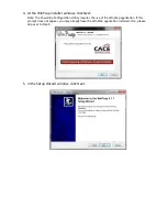
Page 16: ...t Note The Powerline Configuration Utility requires the use of the WinPcap application If this prompt does not appear you may already have the WinPcap application installed If so please skip over to Step 9 5 In the Setup Wizard window click Next ...

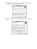
Page 17: ...6 In the License Agreement window click I Agree 7 In the Install Options window click Install 8 At the Setup Wizard Completion window click Finish ...

Page 18: ...RENDnet Powerline Configuration Utility installation window will appear automatically At the Setup Wizard window click Next 10 In the License Agreement window check the radio button I Agree and then click Next ...

Page 19: ...11 In the Select Installation Folder window click Next 12 In the Confirm Installation window click Next 13 At the Installation Complete window click Close ...

Page 20: ...be used to input into the utility This is located on the Device Label please refer to Section 1 4 Enter the 16 digit Device Password DPW for each Remote Device in the utility 1 Click one of the Remote Devices in the list 2 Click Enter Password Remote Devices Powerline adapters that are connected to the selected Local Device across the electrical system Local Device The closest powerline adapter s ...

Page 21: ...d next to the device under Password Note If the incorrect Device Password is entered you will receive an error message Click Enter Password and try entering the password again 5 Repeat steps 1 4 for any remaining Remote Devices 6 Once all of the Device Passwords DPW are entered into the utility changes can be applied to the Remote Devices using the utility ...

Page 22: ...f the powerline adapter s Note If you had previously used the Sync button procedure in generating a random network name security key This will display Unknown Networkname Applies changes to Local Device only Note If you choose this option you will disconnect the Local Device from the Remote Devices Applies changes to Local Device and Remote devices Note If you have not entered the DPW for all remo...

Page 23: ...wall power outlet instead of a power strip or surge protector Connecting the TPL 307E to a power strip or surge protector may degrade network performance or completely stop network signals The TPL 307E is not recommended for use on GFI protected outlets and electrical systems with AFCI circuit breakers as these items may filter out powerline signals The TPL 307E should not be used in areas with ex...

Page 24: ...uP Operation Standby Mode Disconnect the Ethernet cables from the device Ethernet ports and after 3 minutes the device will enter standby mode The Power PWR LED will flash every 15 seconds to indicate that the device is currently in standby mode To return to active mode reconnect the Ethernet cables to the device Ethernet ports and the device will re enter active mode ...

Page 25: ... Nodes Up to 6 max Overlapping Powerline Networks Supported Up to 4 per electrical system Coverage Up to 300 m 984 ft Security 128 Bit AES Advanced Encryption Standard LED Power PWR Powerline PL with Connection Quality Indication Best Green Better Amber Good Red No connection Off Ethernet ETH Connection Solid Blinking Off Buttons Sync Reset Dimension L x W X H A 122 x 55 x 60 mm 4 8 x 2 2 x 2 4 in...

Page 26: ...apters nodes for streaming video across your network 200Mbps is the maximum theoretical Powerline data rate Actual throughput will vary depending on environ ment Networked Powerline devices need to be plugged into power outlets that are on the same electrical system GFCI outlets and AFCI circuit breakers may degrade Powerline network signals ...

Page 27: ...products Products that are sent to TRENDnet for RMA service must have the RMA number marked on the outside of return packages and sent to TRENDnet prepaid insured and packaged appropriately for safe shipment Customers shipping from outside of the USA and Canada are responsible for return shipping fees Customers shipping from outside of the USA are responsible for custom charges including but not l...

Page 28: ...se codes are subject to the GNU General Public License GPL or GNU Lesser General Public License LGPL Go to http www trendnet com gpl or http www trendnet com Download section and look for the desired TRENDnet product to access to the GPL Code or LGPL Code These codes are distributed WITHOUT WARRANTY and are subject to the copyrights of the developers TRENDnet does not provide technical support for...

Page 29: ......

Reviews: