background image

TV-IP512WN Wireless N Internet Camera Server with 2-way Audio


29 

4.  Verify that the “Use proxy server” option is NOT checked. If it is checked, click in the 

checked box to deselect the option and click 

OK

Login 

To access the web manager directly from a computer or 
on a network without a DHCP server running, use the 
default IP address of the camera in the browser address 
entry to access the web manager. Type 

http://192.168.10.30 

in the address bar and press 

Enter

The login dialog appears when accessing the camera.  

Type the default user name “admin”, default password 
“admin” and click on the 

OK

 button to access the 

camera’s management interface.  


Web Manager and Live Video Display Page 

The live video display appears after successful logging in to the web manager. 

Summary of Contents for TV-IP512WN - ProView Wireless N Internet Surveillance Camera

Page 1: ......

Page 2: ...SETUPWIZARD 15 USING THE CAMERA WEB MANAGER 28 Accessing the Camera Video Display 28 Login 29 Web Manager and Live Video Display Page 29 Live Video Display User Interface 30 Camera Configuration Setup 33 Network Settings 34 Wireless Setup 36 Image Setup 37 Video and Audio Settings 39 Motion Detection 40 Time and Date 41 Recording 43 System Configuration 48 Back Up and Restore Camera Settings 50 Fi...

Page 3: ...PLAYING VIDEO FILES ON A COMPUTER 65 Load Saved Video Files 66 Play Video Files 68 ffdshow 69 TECHNICAL SPECIFICATIONS 75 I O TERMINAL APPLICATION 79 ...

Page 4: ... for proper installation of your new Wireless Network Camera Have all the necessary information and equipment on hand before beginning the installation Packing List Open the shipping carton and carefully remove all items In addition to this Manual ascertain that you have One TV IP512WN Wireless Network Camera One Camera Stand One Power Adapter One Ethernet Cable One Installation CD ROM containing ...

Page 5: ... Ethernet Network Interface Card o For wireless connections 802 11 series Wireless Interface Card CD ROM Drive for Setup Wizard on Installation CD ROM IPView Pro 2 0 Application Users must use Microsoft Windows 2000 XP or Vista Operating System with Internet Explorer 6 0 or above with DirectX9 0 Network Local Area Network 10Base T Ethernet or 100Base TX Fast Ethernet Wireless Local Area Network IE...

Page 6: ...sword you will be prompted to enter when you access the configuration windows using a Web browser The default Password is admin IP address This is the IP address you will enter into the Address field of your Web browser to access the camera monitor screen and configuration menus using a Web Browser The camera uses DHCP for IP settings by default If a DHCP server is not detected the default IP addr...

Page 7: ...e front of the camera can be turned on remotely to illuminate an area immediately in front of the camera Live audio for listen and speaking The built in mic is useful for listening for noise or voices in front of the camera The sensitivity can be adjusted to pick up faint noise An audio output connection allows use of external speakers for two way communication from the operator s station Supports...

Page 8: ...nel of TV IP512WN LED Indicators LNK This LED indicator lights steady orange when a valid Ethernet link is established It blinks orange when traffic is received or transmitted through the Ethernet link PWR This LED indicator lights green when the camera is powered on It remains dark when powered off Link LED indicator Power LED indicator Audio mic Adjustable focus camera lens ...

Page 9: ...era when fitted with the Infrared lens is split between the camera body and lens using the power connection adapter cable attached to the infrared lens All other cables connect to the camera at the rear panel Rear Panel view of TV IP512WN Antenna Reset button Power receptacle Ethernet Port Audio Line Out Antenna GPIO ...

Page 10: ...ne Out The audio line out receptacle is a mini plug audio connection for speakers GPIO The I O connectors on the rear panel I1 and I2 are for input O are for output 485 are for RS 485 these provide the physical interface used to send and receive digital signals to a variety of external alarm devices such as motion or event sensors Antenna Two threaded posts are used for attaching the antennas Fast...

Page 11: ...nd moisture excessive heat direct sunlight and cold Make sure the power adapter and cord and Ethernet cable are safely arranged so they do not create a tripping hazard and will not be disturbed by people or objects moving past Attach Camera to Stand The camera is shipped with a camera stand The swivel ball screw head on the stand can be attached to the bottom screw hole of camera The swivel ball m...

Page 12: ...just to the speed 10 or 100 Mbps and polarity MDI II or MDI X of the connection Connect Power and Power On Camera To provide power to the camera connect the AC power adapter to the DC power input connector also located on the camera s left side panel and then plug it to the electrical outlet As with any electrical device make sure the power source and camera are located in an area where it is not ...

Page 13: ...era will then automatically reboot itself Upon restarting the camera loads the factory default configuration settings The default IP address 192 168 10 30 and subnet mask 255 255 255 0 will be applied unless a DHCP server is actively connected to the network The administrator s default user name is admin and the password is admin Use the Setup Wizard shipped with the camera to reconfigure it or ac...

Page 14: ...Internet Camera Server with 2 way Audio 14 SD Card Slot SD Card Slot The built in SD card slot allows you to insert Secure Digital Cards This enables images taken by the camera to be saved to an external SD card SD Card Slot ...

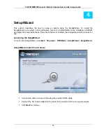
Page 15: ...the installation CD ROM and follow the setup instructions Once the software is installed the SetupWizard utility is ready for use Launching the SetupWizard To launch the SetupWizard click Start Programs TRENDnet SetupWizard SetupWizard SetupWizard Install Your Camera Connect the camera to your LAN using the provided RJ45 cable Connect the AC Power Adapter to the back of the camera and to a live po...

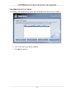
Page 16: ...Internet Camera Server with 2 way Audio 16 SetupWizard Select Your Camera The following screen appears showing the cameras that have been found on your network Click on the camera you want to configure Click Next to continue ...

Page 17: ...2 way Audio 17 SetupWizard Authentication On the following screen type in the ID and Password that you will use to configuring the camera settings Type a User ID in the ID field Type a password for the User in the Password field Click Next to continue ...

Page 18: ...n password Carry out the following if you want to change the admin password Tick the Change Password checkbox Type in a New Password in the New Password field and confirm it in the Confirm Password field Click the Next button to proceed to the next Setup window If you don t want to change the admin password leave the checkbox un ticked and click Next ...

Page 19: ...io 19 SetupWizard Select a Connection Option The following window allows you to specify the connection method used by your camera network Click the radio button of the network environment your camera is connected to The available options are PPPoE DHCP Fixed IP ...

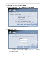
Page 20: ...n method is PPPoE click the PPPoE radio button and click Next The following window appears Type the User Name used to connect to your PPPoE connection in the User Name field Type the Password of the PPPoE User Name in the Password field and confirm it in the Confirm Password field Click Next to proceed to the next setup window ...

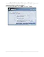
Page 21: ...TV IP512WN Wireless N Internet Camera Server with 2 way Audio 21 SetupWizard Select a Connection Option DHCP If your connection method is DHCP click the DHCP radio button and click Next ...

Page 22: ...ion Fixed IP If your connection method is Fixed IP click the Fixed IP radio button The following window appears Type in the IP Address Subnet Mask Default Gateway Primary DNS Server IP address and Secondary DNS Server IP Address in the appropriate fields Click Next to proceed to the next setup window ...

Page 23: ... way Audio 23 SetupWizard Setup Wireless After choosing your connection method the following window appears Choose if you want to connect to your camera using the wireless connection or not by clicking the appropriate radio button Click Next to continue ...

Page 24: ...Re Scan button to scan for additional Wireless LAN s Type the SSID of the WLAN you want to connect to in the SSID field Choose the Wireless Mode of your WLAN from the Wireless Mode drop down menu Choose the Channel of your WLAN from the Channel drop down menu Choose the Authentication method of your WLAN from the Authentication drop down menu Choose the Encryption method of your WLAN from the Encr...

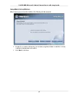
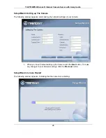
Page 25: ... you to configure additional camera settings Type a name to help you identify the camera in the Camera Name field Set the camera date and time from the Camera Time drop down menus To use the time settings from your computer click the Copy Local Time button Click Next when you have finished configuring the other settings ...

Page 26: ...ollowing window appears summarizing the network settings of your camera When you have finished setting up the Camera click the Next button To make any changes to your Camera settings click the Previous button SetupWizard Camera Restart The following window appears indicating that the camera is restarting ...

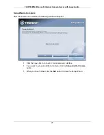
Page 27: ...mplete After the camera has restarted the following window will appear Click the hyper link to connect to the camera web interface If you want to setup an additional camera click the Setup Another Camera button When you have finished click the Exit button to close the Setup Wizard ...

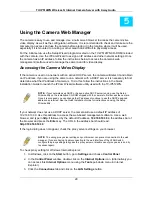
Page 28: ...s DHCP or has an active DHCP server running use the Setup Wizard utility on the installation CD ROM shipped with the camera to first access the camera Once it is accessed you can change the IP address or continue to use the DHCP assigned address as preferred See the Quick Installation Guide for instructions on using the Setup Wizard utility If your network does not use a DHCP server the camera wil...

Page 29: ...hout a DHCP server running use the default IP address of the camera in the browser address entry to access the web manager Type http 192 168 10 30 in the address bar and press Enter The login dialog appears when accessing the camera Type the default user name admin default password admin and click on the OK button to access the camera s management interface Web Manager and Live Video Display Page ...

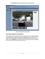
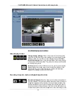
Page 30: ...control snapshot and recording of video and audio controls Links to other management menus are located at the top right porting of the interface Click the SETUP link to view menus used to configure various camera settings including advanced video wireless and network configuration settings Click the SYSTEM link to view menus used for device management firmware upgrades device logs device reset and...

Page 31: ... Click on the Full Screen icon to use the entire monitor display area for live video output Use the left click button on the mouse with the cursor placed at the top bottom left and right edges of the display to pan and tilt the view Recording Snapshot Audio and Digital Output Controls Record and Snapshot Use the camera icon to take a snapshot of the video display This will immediately cause the sc...

Page 32: ... audio through connected speakers This is disabled by default Digital Output control Click to enable or disable the Digital Output Port This icon will appear yellow if the Digital Output port is enabled Event Indicators Digital input indicator This appears yellow when the digital input mechanism is active This requires a device or devices to be connected to the camera via the I O terminal Motion d...

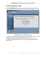
Page 33: ...d other settings for the camera Setup Wizard menu in Configuration directory To configure the camera with the web manager s setup wizard click the Next button and follow the instructions in the menus to configure network time and name settings To configure these settings without using the wizard click on the link for the settings to be configured to view the configuration menu These menus are pres...

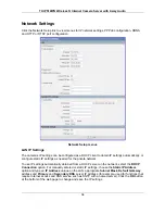
Page 34: ...P settings as needed for the private network To use IP settings automatically obtained from a DHCP server on the network select the DHCP Connection option For manually entered or static IP settings choose the Static IP Address option and type an IP Address unique on the LAN appropriate Subnet Mask Default Gateway address and Primary and Secondary DNS server IP address for example used for function...

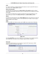
Page 35: ... used by your network in the External HTTP port and External RSTP port fields PPPoE For PPPoE client Internet access tick the Enable PPPoE checkbox and enter the user name and password used for the PPPoE connection Click the OK button at the bottom of the web page to apply the PPPoE account settings DDNS If a Dynamic DNS account has been setup use the DDNS menu to enter account information DDNS me...

Page 36: ... networks To connect one wireless network scroll up and down in the list and highlight to select the desired network and it is listed in the SSID field Click Rescan to conduct a new search for available networks SSID The Service Set Identifier SSID is the name assigned to the wireless network It will auto detect and display the SSID of wireless network connected in this box This default setting wi...

Page 37: ...default setting is 42 Contrast Adjust the contrast level The value range is from 0 100 increments of 20 The default setting is 100 White balance White balance is enabled Auto by default if desired it can be disabled here Flip Use this to flip the image upside down This is used with the Mirror option if the camera is mounted in a hanging position as from a ceiling Saturation Adjust the color satura...

Page 38: ...and white only display that is no color is displayed in the video Mirror Use this to produce a mirror image display This is used with the Flip option if the camera is mounted in a hanging position as from a ceiling Reset to Default Click this button to reset the TV IP512WN Image Settings back to factory defaults ...

Page 39: ...e in low light situations To enable Night Mode tick the Enable Night Mode checkbox Choose a value in seconds to specify how long the shutter will remain open after the camera flashes from the Shutter drop down menu This is useful in low light situations as it allows you to get more ambient light from the background allowing you to see more detail from both the subject and background of your video ...

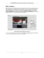
Page 40: ...and use the mouse and left mouse button to draw a rectangular area The drawn area appears as a red box on the display in the Motion Detection menu Click the Enable Video Motion box to check mark it and click the OK button Sensitivity level can be set by typing a value from 0 100 with 100 being the most sensitive Motion detection menu drawn area in red To remove an established drawn motion area sel...

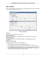
Page 41: ...eckbox Auto Daylight Saving If enabling Daylight Saving Time click this radio button to adjust Daylight Saving Time automatically Set date and time manually If enabling Daylight Saving Time carry out the following Click this radio button to manually adjust Daylight Saving Time Use the Offset drop down menu to set the Daylight Saving adjustment that will be used Set the Start time and End time of t...

Page 42: ...the NTP Server URL in the NTP Server textbox Set date and time manually Click this radio button to specify that the date and time will be set manually Use the drop down menus to select the current the Year Month Day Hour Minute and Second Alternatively you can automatically fill in the drop down menus with the current date and time from your computer by clicking the Copy Your Computer s Time Setti...

Page 43: ... network drive SD Card This option specifies that the recording will be saved to the SD Card in the SD Slot on the side of the camera Samba network drive This option specifies that the recording will be saved to a Samba drive on your network Samba Auth Use the drop down menu to specify whether a user name and password is required to access the Samba drive If no user name or password is required to...

Page 44: ...ling Snapshot scheduling includes three options snapshots can be Event Based Images are created based on triggering events motion detection and digital input signal via I O terminal Continuous FTP only Images are created at set intervals and sent to an FTP server The intervals determine how often the snapshots are made and are configured in the FTP Server setup menu Scheduled FTP only Images are c...

Page 45: ... the snapshot e mails Test Click this button to send a test e mail from the TV IP512WN to the specified recipient e mail address to verify that all the credentials have been configured correctly Tick the FTP Server checkbox to specify that the images will be sent to an FTP Server Configure the parameters as described below User Name Type the User Name of your FTP account Password Type the password...

Page 46: ...ble digital output triggered by motion detection or an input signal through the I O terminal The digital output signal is typically used to activate another device such as lights alarm or some type of notification For example a device connected to the I O terminal might be triggered when a door is opened Digital Output With the digital output enabled from a D I Signal trigger event a light switch ...

Page 47: ...e remaining settings to make sure they are compatible with the RS 485 device Refer to the manufacturer s instructions included with the RS 485 device When the Pan Tilt stand is properly connected and the RS 485 settings are compatible the main user interface will include directional control arrows used for pan and tilt control of the stand Directional View Controls in the main User Interface Home ...

Page 48: ...ration The System configuration menus include the Device Management menu Device Management menu Admin Password Setting Use this section to change the Admin Password for the camera Type in a New Password and confirm it in the Retype Password field Click Save to set the new password ...

Page 49: ...usly User List Use this section to delete existing users Users can be removed by selecting the name from the User Name drop down menu and clicking the Delete button Device Setting Use this section to change the following Camera settings Camera Name This parameter sets the name of your camera You can use this to type a name to help you identify the camera e g Front Door could be used if your camera...

Page 50: ... From Local Hard Drive To load a previously saved configuration settings file click the Browse button to Load From Local Hard Drive to locate the file and then click the Load Configuration button It will take a few seconds to load the new settings The camera will then restart Restore To Factory Defaults To restore the camera to the factory default configuration settings click the Restore Factory D...

Page 51: ...ade the camera firmware make sure the correct firmware file is located on your computer Click the Browse button to locate the file After locating the file click the Upload button to load the file It will take several seconds to load the firmware and restart the camera Firmware Upgrade menu ...

Page 52: ...ion MAC address and firmware version is displayed in the Device Information display Device Information display Log Click the Log link to view the camera s current log To save the log in simple text form on your computer click the Download button Click Clear to delete all entries in the log Camera Log ...

Page 53: ...s Once the software is installed the IP Cam Center camera monitoring utility is ready for use Add up to 32 network cameras to monitor using the software Additional software IPCam Player software is also installed The IPCam Player is used for playing recorded video from cameras that have been configured to save recorded files Launching IPView Pro 2 0 for the first time To launch IPView Pro 2 0 clic...

Page 54: ...sh button to conduct another search If it still does not appear check the IP address of the camera and click on the Input the location of camera menu tab and skip ahead to step 2 1 2 Select the camera to add from the list enter the administrator s user name ID and password a preview of the live video display will appear Click the OK add this camera button a confirmation message informs when the ca...

Page 55: ...zard software for the camera and verify the correct IP address Click Exit to return to the main Add camera menu 3 Once the cameras have been added they are ready to be used in the main IPView Pro 2 0 user interface Close the Add camera menu click Exit to go to the main user interface See below for a description Type the IP address of the camera Enter user name and password for camera being added ...

Page 56: ...ed to exit 3 Pan and Tilt control cameras using RS 485 Pan Tilt device only Click directional arrows to move camera in that direction within the limits of the pan and tilt range The in the center of the control is used to return to the home or center view as configured for the camera 4 Snapshot recording and audio controls See below for detailed information 5 Live video display controls See below ...

Page 57: ...l photo camera icon is used to take a snapshot of the selected live video display The video camera icon is used to begin video recording of the selected live video display Snapshot and videos files are stored in a default folder on the administrator s system or in a folder designated by the administrator The audio controls are represented by a microphone icon to activate the internal mic or the au...

Page 58: ...ays appear in the interface move the cursor over a display you want to change and right click A dialog appears see example below The top most option in the dialog allows the user to Replace content by followed by a list of connected camera IP addresses or URL locations Select the camera display you want to occupy the position the cursor is placed over The display position will then be swapped with...

Page 59: ...rding options email alerts and other network settings Adding a Camera The procedure to add a camera after the initial launch of the software is very similar to the procedure used during the first setup Follow the instructions below to add cameras To add a camera 1 Click the Configuration icon to view the Camera Setup menu The top most tab of the menu is the Camera Management tab A list of active c...

Page 60: ...ra added now appears in the Camera List To launch the web manager for the newly added camera or any camera in the active camera list select it and click the Browse Selected Camera button Removing a Camera To remove the camera from the list of active 1 Select the camera you want to remove 2 Click Delete Selected Camera Note Any camera display can be removed from the main IPView Pro 2 0 user interfa...

Page 61: ...in the Camera Settings menu tab To apply an existing schedule template click the Select button and choose a schedule from the list of previously created schedule templates If a new schedule is needed it can be created from the Select Schedule Template menu See below Create Schedule Templates To make a new schedule template click the Create Template button to view the Create Schedule Profile menu U...

Page 62: ...al Input control Each menu has the schedule option to apply a schedule for the action taken or always take the specified action For Motion Detection use the Config motion detection area menu to create the monitor area by clicking on the applicable location in the image Check the Activate MD to enable motion detection feature and draw the area that you want to monitor Save settings once done ...

Page 63: ...ge allowed memory storage disk space and for video file management Recorded files can be limited by time elapsed or by size Use the select storage folder to choose an alternative destination for stored video files Storage limits can be set for each camera by time elapsed or hard disk space allowed A limit can also be placed for the system and all cameras used in IPView Pro 2 0 ...

Page 64: ...less N Internet Camera Server with 2 way Audio 64 IPView Pro 2 0 Miscellaneous Options The Other Options available for configuration include Proxy server setup email notification scan interval and alert type settings ...

Page 65: ...of codecs used for media files There is an ffdshow installation file on the CD shipped with the camera Install ffdshow before using the IPCamPlayer For information on installation and use of ffdshow see the ffdshow section at the end of this chapter The IPCamPlayer can be launched directly from the IPCamCenter or from the Programs menu To launch the program from the IPView Pro 2 0 interface click ...

Page 66: ...ally for storing video files These files are normally located in the My Documents folder in Windows The file folders are named according to the IP address and camera model For example 192 168 0 20_TV IP512WN is the name of the file folder for the TV IP512WN using the default non DHCP IP address IPCamPlayer User Interface 1 2 4 3 ...

Page 67: ...d Delete files from list Use the Search Files button to add recorded video files A new menu pops up that is used to find and add files to the list See description on next page 4 Playback controls Standard video playback controls for Stop Play Pause go to next file or go to previous file Faster and Slower to control speed of playback Playback can be slowed to as much as 1 8 normal speed or speeded ...

Page 68: ...a Digital Input device When the search criteria have been defined click the Search button to place qualified files in the Search list Choose the files to be added to the view file list by check marking the individual files or click the Select All button to check mark all files in the Search list click Add to place the check marked files on the list of files for viewing After the files to be viewed...

Page 69: ...ffdshow installation are all that is needed Expert users can change audio and video codecs as desired with one of the three ffdshow configuration utilities installed along with the codecs The configuration utilities can be accessed after installation from the ffdshow folder in the Programs folder Start Programs ffdshow configuration utility Install ffdshow 1 Insert the CD ROM into the CD ROM drive...

Page 70: ... Server with 2 way Audio 70 3 The InstallShield Wizard will appear click Next in the welcome screen 4 Accept the default location Windows Programs folder on the system for placement or Browse to choose an alternative Click Next to continue ...

Page 71: ...5 Click to check the components that will be installed For IPCamPlayer it is only necessary to use the default components already selected Click Next to continue 6 Accept the default destination folder ffdshow or Browse to choose an alternative Click Next to continue ...

Page 72: ...tasks that will be installed For IPCamPlayer it is only necessary to use the default formats already selected Click Next to continue 8 Click to check the video applications that use ffdshow For IPCamPlayer it is only necessary to use the default applications already selected Click Next to continue ...

Page 73: ...it is only necessary to use the default applications already selected Click Next to continue 10 Choose a speaker setup or choose Disable mixer if unsure The audio function will work regardless of what speaker setup is chosen Usually it will choose the default arrangement used on system on which it is being installed Click Next to continue ...

Page 74: ... the necessary codecs The installation will take a few seconds 12 If desired any of the three configuration utilities included with the ffdshow installation can be launched by checking the appropriate box Click Finish to complete the installation NOTE To download the latest copy of ffdshow please check the ffdshow website http ffdshow en softonic com ...

Page 75: ...ni directional microphone Sensitivity 48dB 3dB 5 meters max Frequency 50 16000Hz S N 50dB External speaker output Two way audio with echo canceling Codec ARM PCM Image Video Compression MPEG 4 MJPEG Profiles up to 4 profiles simultaneously Exposure white balance control automatic Resolution VGA 640x480 QVGA 320x240 QQVGA 160x120 up to 30fps I O Connector Input 2 sets pin 1 2 pin 3 4 Output 1 set p...

Page 76: ...e Opera Netscape and Google Chrome To Run Software Windows XP Vista IPView Pro 2 0 Channel supports up to 32 cameras Record Playback Motion Detection Audio Network Protocols IPV4 ARP TCP UDP ICMP DHCP Client NTP Client DNS Client DDNS Client SMTP Client FTP Client HTTP Server Samba Client PPPoE UPnP AV RTP Real Time Protocol RTCP Real Time Control Protocol RTSP Real Time Streaming Protocol Wireles...

Page 77: ...ing type MPEG 4 and MJPEG Resolution 640 x 480 320 x 240 160 x 120 Frame rate 1 2 3 5 10 15 30 Fixed bit rate 64k 128k 256k 384k 512k 768k 1M 1 5M 2M Profile 3 Encoding type MJPEG Resolution 640 x 480 320 x 240 160 x 120 Frame rate 1 2 3 5 10 15 30 Fixed bit rate 64k 128k 256k 384k 512k 768k 1M 1 5M 2M Profile 4 for mobile device only Encoding type MPEG 4 Resolution 640 x 480 320 x 240 160 x 120 F...

Page 78: ...TV IP512WN Wireless N Internet Camera Server with 2 way Audio 78 RTSP port 554 default Digital Zoom 16x Dynamic DNS Yes Time Synchronize with NTP server or set time date manually ...

Page 79: ...coupled input Connector Pin Assignment Sign FUNCTION SPECIFICATION O Photo Relay OUTPUT Common Close circuit current maximum 120mA Peak load current Open circuit voltage maximum 350V Peak AC O Photo Relay OUTPUT Normal Open I1 Photo Relay INPUT Active High voltage 5 40VDC Dropout voltage 0 VDC I1 Photo Relay INPUT I2 Photo Relay INPUT Active High voltage 5 40VDC Dropout voltage 0 VDC I2 Photo Rela...

Page 80: ...with 2 way Audio 80 Interface Schematic 1 Output device load is driven by external power supply 2 Input device active control device has independent power supply 3 RS 485 Interface Swivel stand RS 485 RS 485 DI DI DO DO Load AC DC RS485_A RS485_B ...

Page 81: ... of the dated proof of the purchase Products returned to TRENDware must be pre authorized by TRENDware with RMA number marked on the outside of the package and sent prepaid insured and packaged appropriately for safe shipment WARRANTIES EXCLUSIVE IF THE TRENDWARE PRODUCT DOES NOT OPERATE AS WARRANTED ABOVE THE CUSTOMER S SOLE REMEDY SHALL BE AT TRENDWARE S OPTION REPAIR OR REPLACEMENT THE FOREGOIN...

Page 82: ...n and Power Supply carry 1 year warranty Some TRENDnet products include software code written by third party developers These codes are subject to the GNU General Public License GPL or GNU Lesser General Public License LGPL Go to http www trendnet com gpl or http www trendnet com Download section and look for the desired TRENDnet product to access to the GPL Code or LGPL Code These codes are distr...

Page 83: ...TV IP512WN Wireless N Internet Camera Server with 2 way Audio 83 ...

Reviews: