MBS1000 Installation Guide
Trenton Systems, Inc.
3-4
Slide Rail Installation (continued)
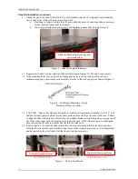
NOTE 1:
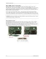
Lift the lever on the left slide rail UP while moving the right slide rail lever
DOWN while sliding the chassis into the slide rails in order to move the chassis
completely into the component rack.
NOTE 2
: To remove the chassis from the component rack slides, lift the lever on the left
slide rail UP while moving the right slide rail lever DOWN while sliding the chassis out
of the slide rails.
15.
Check slide rail alignment for any signs of binding by slide the chassis into and out of the
component rack. A binding condition indicates undue slide rail stress or misalignment. Adjust
slide rail positions until the chassis movement is smooth. Tighten all screws and the depth
adjustment nuts to complete the installation.
C
ONNECTING
AC
P
OWER
–
MBS1000-002
S
YSTEM
C
ONFIGURATION
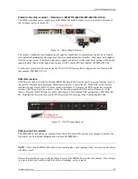
The MBS1000-002 configuration requires a single-phase power source providing 100-240VAC at 50 to
60Hz to
each
AC input power outlet located at the rear of the chassis for the incoming AC power
implementation of this power supply configuration. Power must be available at both three-pin AC input
receptacles located at the rear of the system. An over-current protection device shall protect each power
cord. Under this incoming power connection scenario the power supply de12VDC and +12VDC
AUX to the system at 73.8A and 2.5A respectively. Total output power must not exceed 900W.
To connect AC power to the server:
1.
Establish a chassis to earth ground connection to the MBS1000 chassis.
2.
Connect the AC power cords to the AC receptacles.
3.
Connect the plug end of the power cords into the main outlets.
NOTE:
The system’s power monitoring circuits will shut the system down if the maximum current
limit is are drawn from the power supply for the system supply’s 12VDC and 12VAUX power rails.
C
ONNECTING
DC
P
OWER
–
MBS1000-001
S
YSTEM
C
ONFIGURATION
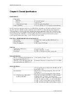
The MBS1000-001 configuration requires a -48VDC power source connected to
each
three-position
connector on the -48VDC power supplies. Power must be available at both three-position DC connectors
located at the rear of the system.
Each DC supply must have an incoming power source of:-48 to -60VDC, 20.4A DC typical, and the
maximum input current must not exceed 23A. The -48VDC power supply option de12VDC and
+12VDC AUX to the system at 61.5A and 2.5A respectively. Total output power must not exceed 750W.


