MBS1000 Installation Guide
3-5
Trenton Systems, Inc.
C
ONNECTING A
V
IDEO
M
ONITOR
,
R
EAR
E
THERNET AND
USB
TO THE
MBS1000
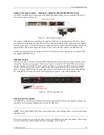
The figure below illustrates various connection points to the rear system I/O and network communication
functions available on the system’s MBC8240 single board server blade. Follow the connection label
located below the MBC8240 SBC to make the necessary connections for your specific MBS1000
application. Note that the orange Ethernet LAN cable in the illustration below is connected to Ethernet Lnk
0. This LAN port indicated; by the black connection label identifier, is dedicated to the system
management function and cannot be used as a general purpose Ethernet LAN.


