background image

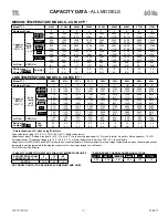
MEDIUM TEMPERATURE MODELS - CAPACITY *

* Derate capacity by 5% when using EC Motors

Model TTL

010M

015M

020M

025M

032M

038M

060M

077M

115M

Number of Fans

1

1

1

1

1

1

2

2

3

Capacity 

BTUH 

(WATTS)

Evap 

Temp.

25°F 

(-4°C)

R407A

R448A

900

1380

1900

2380

3040

3600

5700

7300

10900

(264)

(404)

(557)

(696)

(891)

(1058)

(1670)

(2144)

(3202)

R407C

860

1305

1800

2250

2880

3420

5400

6900

10400

(250)

(383)

(527)

(660)

(844)

(1003)

(1582)

(2031)

(3033)

R404A

R507

950

1450

2000

2500

3200

3800

6000

7700

11500

(278)

(425)

(586)

(733)

(938)

(1114)

(1758)

(2257)

(3370)

R22

900

1380

1900

2380

3000

3600

5700

7300

10900

(264)

(404)

(557)

(696)

(891)

(1058)

(1670)

(2144)

(3202)

R134a

855

1305

1800

2250

2880

3420

5400

6930

10350

(250)

(383)

(527)

(660)

(844)

(1003)

(1582)

(2031)

(3033)

Air Flow

CFM (L/s)

130

180

237

270

440

440

928

807

1242

(61)

(85)

(112)

(127)

(208)

(208)

(438)

(381)

(586)

Refrigerant  ** 
Charge  

R407A

Lbs (Kg)

0.4

0.5

0.7

0.8

0.9

1.2

1.4

2.3

3.4

(0.2)

(0.2)

(0.3)

(0.4)

(0.4)

(0.5)

(0.6)

(1.0)

(1.5)

CAPACITY DATA - 

ALL MODELS


LOW TEMPERATURE MODELS - CAPACITY *

Model TTL

009L

013L

017L

021L

028L

033L

052L

066L

099L

Number of Fans

1

1

1

1

1

1

2

2

3

Capacity 

BTUH 

(WATTS)

Evap 

Temp.

-20°F

(-28.9°C)

R407A

R448A

810

1190

1620

2000

2660

3100

4900

6300

9400

(237)

(348)

(473)

(584)

(780)

(919)

(1448)

(1837)

(2756)

R407C

770

1125

1530

1890

2520

2970

4700

6000

8900

(224)

(329)

(448)

(554)

(739)

(870)

(1372)

(1741)

(2611)

R404A

R507

850

1250

1700

2100

2800

3300

5200

6600

9900

(249)

(366)

(498)

(615)

(821)

(967)

(1524)

(1934)

(2901)

R22

810

1190

1620

2000

2700

3100

4900

6300

9400

(237)

(348)

(473)

(584)

(780)

(919)

(1448)

(1837)

(2756)

R134a

765

1125

1530

1890

2520

2970

4680

5940

8910

(224)

(329)

(448)

(554)

(739)

(870)

(1372)

(1741)

(2611)

Air Flow

CFM (L/s)

130

180

237

270

440

440

928

807

1242

(61)

(85)

(112)

(127)

(208)

(208)

(438)

(381)

(586)

Refrigerant  ** 
Charge  

R407A

Lbs 
(Kg)

0.4

0.5

0.7

0.8

0.9

1.2

1.4

2.3

3.4

(0.2)

(0.2)

(0.3)

(0.4)

(0.4)

(0.5)

(0.6)

(1.0)

(1.5)

* CAPACITY CORRECTION FACTORS FOR LOW TEMPERATURE UNITS

SATURATED SUCTION 

TEMPERATURE °F (°C)

(-17.8)

-10 

(23.3)

-20 

(-28.9)

FACTOR

1.06

1.03

1.0

NO CORRECTION FACTOR REQUIRED FOR MEDIUM TEMP. UNITS

Capacities rated using 10°F 

(5.6°C)

 TD & 100°F 

(38°C)

 liquid temperature.

Capacities at other TD within a range of 8 to 15 °F 

(4.4 to 8.3°C)

 are directly proportional to TD, or use formula:  Capacity = Rated capacity ÷ 10 x TD.

For capacities at TD outside of range 8 to 15 °F 

(4.4 to 8.3°C)

, or liquid temperature lower than 75°F 

(24°)

, consult factory.

Capacities for R448A, R407A and R407C are based on mean temperature. Mean temperature is the average temperature between the saturated suction 
temperature and the temperature feeding the evaporator. For dew point ratings, consult factory.
For R449A, use R448A data.

R448A

R407C

R404A

R507

R22

R134a

0.96

0.99

0.92

0.93

1.02

1.03

** REFRIGERANT CHARGE CONVERSION FACTORS

TTL

60Hz

23/06/17

T30-TTL-PDI-16

- 3 -

Summary of Contents for TTL Series

Page 1: ...Resources Service Parts Troubleshooting Warranty etc 15 As Built Service Parts List BACK High Medium and Low Temperature Applications 10 F 23 3 C or Above Box Temperature TTL Two Way Low Profile Evapo...

Page 2: ...rage space Dual refrigeration coils and two way air distribution reduces air velocities to minimize product dehydration Air enters through fan and discharges two ways out of each coil side Rugged heav...

Page 3: ...448 554 739 870 1372 1741 2611 R404A R507 850 1250 1700 2100 2800 3300 5200 6600 9900 249 366 498 615 821 967 1524 1934 2901 R22 810 1190 1620 2000 2700 3100 4900 6300 9400 237 348 473 584 780 919 144...

Page 4: ...1 2 1 5 15 70 0 65 0 81 15 60 530 4 6 5 8 15 021LE S1A 1 1 2 1 5 15 70 0 65 0 81 15 60 530 4 6 5 8 15 028LE S1A 1 1 2 1 5 15 70 0 65 0 81 15 60 0 60 0 75 15 30 750 6 5 8 2 15 033LE S1A 1 1 2 1 5 15 70...

Page 5: ...15ME S2A 1 0 7 0 9 15 60 0 24 0 30 15 50 530 2 3 2 9 15 020ME S2A 1 0 7 0 9 15 60 0 24 0 30 15 50 530 2 3 2 9 15 025ME S2A 1 0 7 0 9 15 60 0 24 0 30 15 50 530 2 3 2 9 15 032ME S2A 1 0 7 0 9 15 60 0 24...

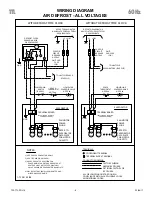
Page 6: ...ER PLUGS REFER TO EVAPORATOR DATA PLATE FOR MOTOR QUANTITY MTR FAN TERMINALS MTR FAN MTR FAN SOLENOID VALVE EVAPORATOR NOTE 4 SPACE THERMOSTAT N C NOTE 4 LIQUID LINE 4 GND F FAN MOTOR POWER PLUGS REFE...

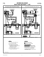
Page 7: ...OR EQUIVALENT 1 CIRCUIT 4 2 3 X N NOTE 3 BREAKER TM FUSE OR DEFROST HEATER L1 C T1 CONTACTOR CIRCUIT BREAKER NOTE 3 N GND L1 FUSE OR USING MAXIMUM 15A HEATER OVERCURRENT PROTECTION FOR ALL MODELS WIT...

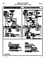
Page 8: ...WIRING DIAGRAM ELECTRIC DEFROST 230V TTL 60Hz 23 06 17 T30 TTL PDI 16 8...

Page 9: ...8 7 8 479 4 1 2 114 14 1 8 359 17 3 4 451 9 3 4 248 12 6 5 7 020M 3 8 1 2 Flare 18 7 8 479 5 1 2 140 14 1 8 359 17 3 4 451 9 3 4 248 13 7 6 2 025M 3 8 1 2 Flare 18 7 8 479 5 1 2 140 14 1 8 359 17 3 4...

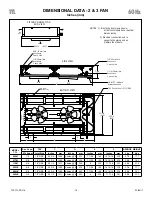
Page 10: ...F 23 5 8 600 C 7 5 8 194 23 3 4 603 DIMENSIONAL DATA 2 3 FAN Inches mm MODEL TTL Suc Conn TXV C D E F APPROX WEIGHT ID Sweat Inlet Size Inches mm Inches mm Inches mm Inches mm Lbs Kgs 060M 1 2 1 2 ODS...

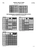
Page 11: ...LL TXV Selections based on 90 100 F liquid MODEL TTL TD R404A R507 R448A R407A R407C R22 010M 10 HF 1 8 SC HF 1 4 HC 15 015M 10 HF 1 8 SC HF 1 4 HC 15 020M 10 HF 1 8 SC HF 1 4 HC 15 HF 1 4 SC 025M 10...

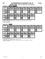
Page 12: ...595 20 3 135 4 940 6 270 9 405 RECOMMENDED EXPANSION VALVE SELECTION MEDIUM TEMPERATURE MODELS SPORLAN R404A MODEL TTL 009L 013L 017L 021L 028L BTUH VALVE BTUH VALVE BTUH VALVE BTUH VALVE BTUH VALVE E...

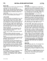
Page 13: ...laws LOCATION The evaporator is designed to be mounted to the ceiling of the box or cabinet Refrigeration piping and electrical connections are routed to the rear sides through the knock outs The uni...

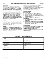
Page 14: ...ost models AD Multiple fans have a junction terminal box for conduit connections INSTALLATION INSTRUCTIONS CONT D When fan delay thermostats are installed the fans may not start up until the coil temp...

Page 15: ...ng t rp com call 1 844 893 3222 x529 web t rp com parts email parts t rp com call 1 844 893 3222 x501 email orders t rp com call 1 844 893 3222 x501 email shipping t rp com call 1 844 893 3222 x503 TT...

Page 16: ...the manufacturer s policy of continuous product improvement we reserve the right to make changes without notice NATIONAL REFRIGERATION AIR CONDITIONING CANADA CORP 159 Roy Blvd Brantford Ontario Canad...

Reviews: