TE0600 TRM
Revision: V3.02
Copyright © 2017 Trenz Electronic GmbH
Page
of
13
33
http://www.trenz-electronic.de
Flash Memory
GigaBee XC6SLX board contains 128 Mb (16 MB) serial flash memory chip Winbond W25Q128FV
(W25Q128BV till REV 02) (U11). This serial flash chip can operate as general SPI memory mode and in
double or quad modes. Usage of dual and quad modes increase bandwidth up to 40 MB/s.
For more information see Winbond W25Q128FV (W25Q128BV till REV 02) product overview.
Flash can be programmed in several ways:
Direct SPI programming via J1 connector.
Indirect SPI programming via FPGA pins, controlled by JTAG.
Direct SPI programming by FPGA, using SPI core.
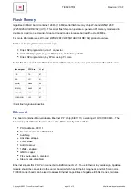
Serial flash is connected to FPGA bank 2 and B2B connector J1; used pins are listed in the table below.
Flash signal
FPGA pin
J1 pin
/CS
T5
87
CLK
Y21
91
DI(IO0)
AB20
95
DO(IO1)
AA20
93
/WP(IO2)
U14
99
/HOLD(IO3)
U13
97
Serial flash signals connection
Ethernet
The board contains a Marvell Alaska Ethernet PHY chip (88E1111) operating at 10/100/1000 Mb/s. The
board supports GMII interface mode with the FPGA. Configuration details:
PHY address – 00111
Do not advertise the PAUSE bit
Auto Neg
Advertise all caps
Prefer slave
Auto crossover
125clk - enabled
GMII to copper
Fiber auto-detect - disabled
Sleep mode - disabled
Ethernet signals from PHY are connected to B2B connector J1. To use Ethernet in your design, GigaBee
module should be connected to the carrier board, which have Ethernet magnetics and RJ45 connector.
TE0603 carrier board can be used to access Ethernet capabilities of GigaBee XC6SLX series modules.


