TE0600 TRM
Revision: V3.02
Copyright © 2017 Trenz Electronic GmbH
Page
of
18
33
http://www.trenz-electronic.de
B2B Connectors Pin Descriptions
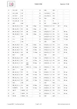
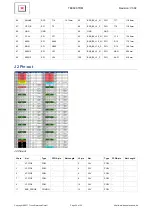
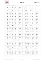
This section describes how the various pins on B2B connectors J1 and J2 connects to TE0600 on-board
components. There are five main signal types connected to B2B connectors:
FPGA users signals;
FPGA system signals;
Power signals;
Ethernet PHY signals;
Other system signals.
FPGA Bank
Single-ended
Differential
Total
VCCIO
Bank 0
1
22
45
VCCIO 0 (3.3 V)
Bank 1
1
6
13
VCCIO 1 (1.5 V)
Bank 2
3
21
45
3.3 V
Bank 3
0
3
6
1.5 V
5
52
109
B2B signals count
Pin Labeling
FPGA user signals connected to B2B connectors are characterized by the "B2B_Bx_Lyy_p" naming
convention, where:
B2B defines a "FPGA to B2B" signal type;
Bx defines the FPGA bank (x = bank number);
Lyy defines a differential pair or signal number (yy = pair number);
p defines a differential signal polarity (P = positive, N = negative); single ended signals do not have
this field.
Ethernet PHY signals use "PHY_name" naming conversions where "PHY" defines signal type "PHY to B2B"
and "name" is PHY signal name.
Remaining signals use custom names.
Pin Numbering
Note that GigaBee XC6SLX have hermaphroditic B2B connectors. A feature of hermaphroditic connector
numbering is that connected signal numbers don't match. Odd signals on module connect to even signals
on baseboard. For example module signal 1 to baseboard signal 2, module signal 2 to baseboard signal 1,
module signal 3 to baseboard signal 4 and so on.

