background image


tres900

 Operations Manual 

Revision G 

www.tresrfsolutions.com 

Transponder and Reader Engineered Systems, Inc 

2142 O’Neal Lane Suite 354 

  Baton Rouge, LA 70816  

  888.574.tres (8737) 

Page 5  


Quick


Start


Guide


Package


Inspection


The shipping package includes a 

tres900

 Reader with a pigtail cable for connecting power and 

communication to and from the Reader, a CD with documentation with programs used for 
setting up and testing the Reader, and an antenna mounting bracket. Please check to confirm all 
items are present upon receiving the reader package. If any questions, please contact our dealer 
immediately or contact our after-sales support directly. 

Appearance


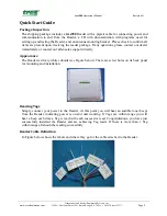
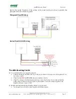
The Reader is silvery white cuboids (see Figure below). There are screw holes on its back panel 
for mounting and installation. 

Reading


Tags


Simply connect your power to the Reader. At this point you will hear an audible tone (beep) 
from the Reader, indicating power is on and unit working. If Tags are within range you will 
hear a beep each time a Tag is read with each successive read. Congratulations, you have just 
successfully installed the Reader and are achieving Tag reads. If there is more than 1 Tag 
within range all should be reading successfully. 

Reader


Cable


Definition


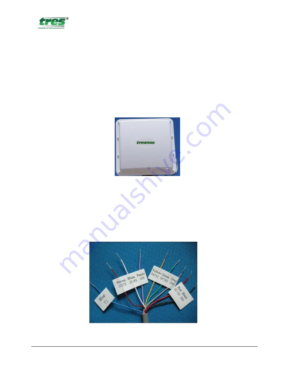
In Figure below shows the labels and where they go for the cable attached to the Reader. 

Summary of Contents for tres900

Page 1: ...and users for integration purposes Proprietary and confidential information is contained within therefore this document is protected by all applicable international intellectual property laws The inf...

Page 2: ...le Definition 5 Reader Cable Color Code Chart 6 Power Requirements 6 WIEGAND OUTPUT 6 Wire Specifications 6 SERIAL OUTPUT RS232 6 Wire Specifications 6 TCP IP ETHERNET OUTPUT 7 PC Configuration 8 Fact...

Page 3: ...atic means to identify physical objects without the need for line of sight communication The main components of a RFID system are tags readers and host computer RFID tags are attached to physical obje...

Page 4: ...thus making it suitable for material management applications Reader The RFID Reader is a device that captures and processes tag data These devices are called readers or interrogators Readers are conne...

Page 5: ...ons please contact our dealer immediately or contact our after sales support directly Appearance The Reader is silvery white cuboids see Figure below There are screw holes on its back panel for mounti...

Page 6: ...own power supply can be used The recommended power supply is the tres PSS12 035 Power Supply 85 264VAC 35W 12VDC 3A regulated which is supplied with each Reader The Reader unit Warranty is based on it...

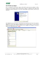
Page 7: ...ry to load a program termed ZNetCom2 66_Setup exe included on the CD in order to setup your preferred properties If you run the setup program Figure below you will see the following Just highlight and...

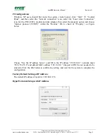
Page 8: ...or the ZNE 100TL module network adaptor then select the property option and choose internet protocol TCP IP within the Routine Tab to check its Property as Figure below Choose Use the IP address below...

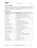
Page 9: ...circular polarized w 0 65 1 0 H V power ratio Max RF Power 30 dBm 1 Watt Power Flatness 0 5 DB RF Power Range 20 30 dBm Software Adjustable Tag ID Modes Timed Mode automatically reads at fixed time T...

Page 10: ...C Personnel Card 3 37 in x 2 125 in x 30 mil tres MM3980 ST Metal Mount tag Blue Plastic casing 3 81 x 1 06 x 56 in tres MMSMST MC Super Slim Metal Mount Tag incl 2 Std Color Logo 1 25 X 375 X 125 tre...

Page 11: ...a tag when the BLUE trigger wire T1 is tied to ground Normal ways to accomplish this is by using Loop Detectors to detect the presence of a vehicle to open a gate or as a safety device to prevent the...

Page 12: ...shooting Guide Q To confirm that the unit is operating properly Confirm the beeper is audible when a good tag is presented or when power is first applied If it is not remove power Check that the RED a...

Page 13: ...ween the tres900 to the host panel Earth Ground should terminate at the back of the Reader through the mounting brackets or through the Readers Power Supply Ground wire negative feed Cable between Rea...

Page 14: ...t to be returned is not received by Transponder Reader Engineered Systems within 30 days of RMA issuance or warranty is determined to be void under the conditions of this warranty statement customer w...

Reviews: