5
c.
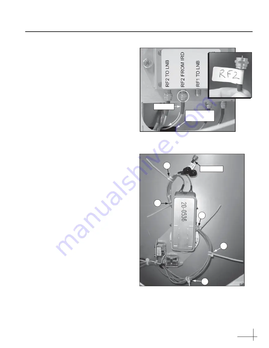
Disconnect the RF cable from the inverter
PCB’s “RF2 FROM IRD” connector (see
d.
Pass the end of the cable through the cable
access hole and route it to the LNB (see
e.
Apply an “RF2” label to the cable (see
f.
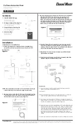
Using five tie-wraps
(supplied in the kit)
,
secure the “RF2”-labeled cable to the cable
bundle at locations 1-5 shown in Figure 7.
Don’t cut the ends of the tie-wraps yet, so you
can easily distinguish these new tie-wraps
from the original tie-wraps.
g.
Using wire cutters, cut and remove the
original tie-wraps at locations 1-5 shown in
h.
Cut the excess ends of the new tie-wraps. Be
sure to collect the trimmings from the
antenna.
Cable Access
Hole
RF Cable
Figure 6: “RF2 FROM IRD” Connector on Inverter PCB
RF2 Cable
1
2
4
5
3
Figure 7: Cable Bundle Tie-wrap Locations
Continued
Bypassing the Inverter PCB


