8
c.
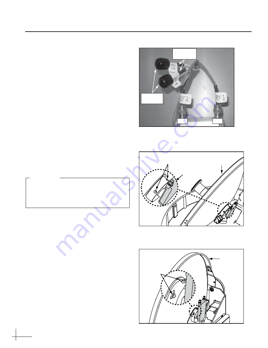
Connect the RF1 and RF2 cables to their
corresponding connectors on the Tri-
Americas LNB (Figure 16).
d. If you are replacing a linear quad-output
LNB
, apply rubber caps over the connectors
of the unused RF3 and RF4 cables to protect
their center conductors (see Figure 16).
e. If the antenna has a serial number later than
080201076:
Using a 2 mm allen hex key,
loosen the two M4 socket set screws securing
the current LNB to the reflector (see
If your antenna has a serial number earlier
than 080201077
, loosen the two wing screws
securing the current LNB to the reflector (see
f.
Remove the old LNB.
g.
Insert the new Tri-Americas LNB fully into
the choke feed with the connectors aligned to
the left, as shown in Figure 19 on page 9.
h. If the antenna has a serial number later than
080201076:
Tighten the two M4 socket set
screws to secure the LNB in place. Apply
9 in-lbs (1 Nm) of torque, if possible.
If your antenna has a serial number earlier
than 080201077:
Tighten the wing screws to
secure the LNB in place.
Connector
Caps
RF2
RF1
RF3 & RF4
Cables
Figure 16: Tri-Americas LNB RF Connectors
M4 Socket
Set Screws
Reflector
LNB
Figure 17: LNB Retaining Screws, Newer Antenna
Figure 18: LNB Retaining Screws, Older Antenna
Wing
Screws
Reflector
Orient the Tri-Americas LNB so that its RF
cable connectors are pointing 90° to the left.
The LNB must be positioned in this manner
to ensure proper operation.
IMPORTANT!
Continued
Installing the Tri-Americas LNB


