19
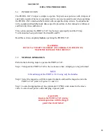
3-2
Unpacking (cant)
Step 3.
Carefully remove the PORTA-TAC and its power pack from the
container, using only the handles for lifting, and set the machine on a
smooth level work surface.
Step 4.
Discard the shipping container, being certain all components have been
removed.
3-3
DROP TUBE AND TRANSFER TIP
Each contact requires its own unique drop tube and transfer tip for optimum contact
transfer during normal operation. These exactly machined components mayor may not be
installed in the PORTA-TAC upon receipt. Also, depending on contact configuration, it
may be necessary to change the drop tube or the transfer tip, or both, for a different
contact.
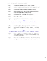
Perform the following steps to install a drop tube or transfer tip:
Step 1.
Unlock and open the hinged panel located on the right side of the
PORTA-TAC. Very carefully remove all packaging material.
Step 2.
Refer to Figure 6-2. Observe if the drop tube is installed. If not, obtain the
appropriate drop tube and install by inserting it firmly through the top of
the PORTA-TAC.
Step 3.
Observe if the transfer tip is installed. If not, obtain the appropriate
transfer tip and install it by inserting the transfer tip into the transfer arm
and securing it by tightening the cap screw.
Step 4.
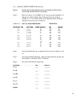
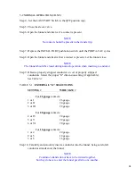
Record in the spaces provided below the data indicated:
CONTACT P/N DROP TUBE P/N
TRANSFER TIP P/N
FUNNEL P/N
Summary of Contents for PORTA TAC E Series
Page 7: ...7 FIGURE 1 1 PORTA TAC CRIMPER FRONT VIEW ...
Page 8: ...8 FIGURE 1 2 PORTA TAC CRIMPER WITH MAGAZINE ...
Page 9: ...9 FIGURE 1 3 PORTA TAC CRIMPER SIDE VIEW ...
Page 11: ...11 ...
Page 17: ...17 ...
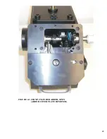
Page 26: ...26 FIGURE 4 1 CRIMP CYLINDER ARBOR OPEN ARBOR COVER PLATE REMOVED ...
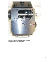
Page 27: ...27 FIGURE 4 1 CRIMP CYLINDER ARBOR CLOSED ARBOR COVER PLATE REMOVED ...
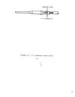
Page 30: ...30 FIGURE 4 3 CRIMP INSPECTION POINTS ...
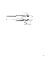
Page 31: ...31 FIGURE 4 4 IMPROPER CRIMPS ...
Page 32: ...32 ...
Page 40: ...40 FIGURE 6 1 PANEL COMPONENTS ...
Page 41: ...41 FIGURE 6 2 CABINET COMPONENTS TRANSFER MECHANISM ...
Page 44: ...44 FIGURE 6 3 INDENTER SYSTEM REPLACEMENT ...
Page 45: ...45 ...
Page 46: ...46 FIGURE 6 5 INDENTER REPLACEMENT ...
Page 50: ...50 ...
Page 53: ...53 ...


