29
Step 20.
Continue inserting the conductor. As the conductor
strands bottom out in the contact, the contact will
be
depressed and, in turn, activate the slide
sensor.
Step 21.
When the
crimping
cycle
is
complete, the funnel will
open; at this
time,
remove the conductor.
NOTE
When the funnel opens, remove the conductor smoothly by simply
pulling it towards yourself. The transfer arm will not retract
until the crimped contact has been removed from the transfer tip.
Step 22.
Inspect the crimp per required specifications
Step 23.
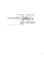
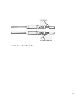
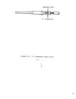
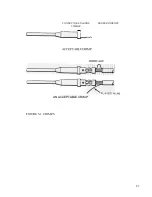
Figures 4-3 through 4-5 are samples of inspection criteria.
Step 24.
Repeat Steps 12 through 22 for each conductor wire
gauge to obtain necessary specimens; inspect per
established procedure.
NOTE
Immediately prior to the last crimp of a given contact being
made, set the LAST PART Switch to the ON (down) position.
Step 25.
Open the sleeve valve.
4-3
PERIODIC CRIMP VERIFICATION
Perform Periodic Crimp Verification in the same manner as
the Initial Crimp Verification. Users may desire to prepare
an equipment data sheet upon which "G" and "T" pull-test
results can be recorded.
Summary of Contents for PORTA TAC E Series
Page 7: ...7 FIGURE 1 1 PORTA TAC CRIMPER FRONT VIEW ...
Page 8: ...8 FIGURE 1 2 PORTA TAC CRIMPER WITH MAGAZINE ...
Page 9: ...9 FIGURE 1 3 PORTA TAC CRIMPER SIDE VIEW ...
Page 11: ...11 ...
Page 17: ...17 ...
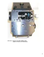
Page 26: ...26 FIGURE 4 1 CRIMP CYLINDER ARBOR OPEN ARBOR COVER PLATE REMOVED ...
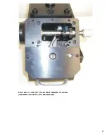
Page 27: ...27 FIGURE 4 1 CRIMP CYLINDER ARBOR CLOSED ARBOR COVER PLATE REMOVED ...
Page 30: ...30 FIGURE 4 3 CRIMP INSPECTION POINTS ...
Page 31: ...31 FIGURE 4 4 IMPROPER CRIMPS ...
Page 32: ...32 ...
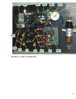
Page 40: ...40 FIGURE 6 1 PANEL COMPONENTS ...
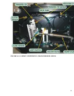
Page 41: ...41 FIGURE 6 2 CABINET COMPONENTS TRANSFER MECHANISM ...
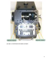
Page 44: ...44 FIGURE 6 3 INDENTER SYSTEM REPLACEMENT ...
Page 45: ...45 ...
Page 46: ...46 FIGURE 6 5 INDENTER REPLACEMENT ...
Page 50: ...50 ...
Page 53: ...53 ...


