Theory of Operation
Section 5
TAC
·
7X
MANUAL
1. Introduction
2. Pneumatic
Supply
The TAC Crimper has been extensively redesigned. The redesign
results in additional logic functions being added to prevent possible
malfunctions, while at the same time reducing the overall number of
components.
All logic, control and operating functions of the TAC Crimper are
performed pneumatically, electrically or both.
The purpose of this Theory of Operation is to provide an overview of
how the TAC operates such that a general understanding of functions
can be achieved. In the event a TAC were to malfunction, familiarity
with its operational sequences will greatly expedite corrective action.
System design is such that many events are sequential and, unless the
TAC is positive a given event has properly occurred, subsequent events
will not occur. This design, in conjunction with high tolerance machined
components, reduces significantly the possibility of initiating crimps on
incorrect contacts, or proceeding to crimp additional contacts if proper
crimp tolerances are not being achieved.
If the crimped contact/conductor is not removed after the crimping cycle
is complete, the TAC will pause. The TAC will remain in the "pause"
position until the contact/conductor is removed.
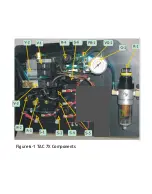
*Please refer to Figure 6-1 & 6-2 while reading this Theory of Opera
tion.*
Air pressure is supplied to the TAC when the operator-controlled
Sleeve Valve (SV) is closed manually.
Electrical power is suppled to the TAC control system via an internally
mounted transformer. Transformer and feeder-bowl power is supplied
from standard 120V outlet (European model 220V). Transformer power
is switched on via switch S-5. Output from the transformer (12V DC) is
supplied to the PLC (control system) of the TAC
!
Summary of Contents for TAC-7AE
Page 6: ...Figure 1 1 TAC 7X Front View ...
Page 8: ... Figure 1 2 Wire Insertion Through Funnel ...
Page 12: ...Figure2 1 Pneumatic Hook Up ...
Page 14: ... Fiqure 2 4 Track Drop Tube Escapement ESCAPEMENT SYSTEM _ _ _ BR ASSEMBL I TRA ...
Page 18: ... ARBOR COVER PLA TE REMOVED Figure 3 1 Crimp Cylinder Arbor Open ...
Page 20: ... ARBOR COVER PLAT E REMOVED Figure 3 2 Crimp Cylinder Arbor Closed ...
Page 23: ... Crimp Inspection Points Improper Crimps ...
Page 33: ...Figure 6 1 TAC 7X Components ...
Page 34: ...Figure 6 2 Control Box Components Figure 6 2 TAC 7X Components Right View ...
Page 37: ...Figure 6 3 Contact Track Feed Air Adjustments ...
Page 42: ... Figure 6 4 Indenter Plate Removal ...
Page 43: ...HOSE CLAMP CAREFULL Y REMOVE Figure 6 5 Indenter Replacement ...
Page 47: ...Figure 6 6 Indenter Adjustment ...
Page 52: ...TAC 7X Pneumatic Diagram ...


