Model 601SBM Low Profile Clamshell
92-0092 Rev. 210701
19
6. OPERATION
Read the operation instructions before operating the Model 601SBM Low Profile Clamshell.
Configure the clamshell for the specific task required.
Mount the Tool Blocks and Tripper Bracket onto the Clamshell.
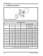
Select and install the proper Clamping Pad Set into the Clamshell. Refer to the section on
‘Clamping Pad Sets’ later in this booklet.
Do not install the Tool Bits until the Clamshell has been installed on the pipe.
Installation of the Clamshell on an In-Line Pipe
Separate the two halves of the Clamshell.
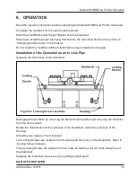
Figure 8: Locking Screw Locations
Disengage the Air Motor by removing the Motor Hold-down Bolt and removing the Air Motor
from the drive socket.
Rotate the Headstock until the split-lines of the Headstock match the split-lines of the
Housing.
Unbolt the two halves of the Clamshell.
Two Locking Screws are located on the Housing and two more on the Headstock. Refer to
‘Locking Screw locations’.
These Locking Screws are captured in their holes so that they will not come totally free of
the Clamshell.
Separate the Clamshell halves evenly by pulling straight apart.
DO NOT FORCE OPEN.
Summary of Contents for 601SBM
Page 1: ...Operation Manual 92 0092 Rev 210701 Model 601SBM Low Profile Clamshell ...
Page 44: ...TRI TOOL INC 92 0092 Rev 210701 42 HOUSING ASSY DRIVE P N 19 0285 5 1 2 4 7 9 8 6 3 ...
Page 46: ...TRI TOOL INC 92 0092 Rev 210701 44 MOTOR ASSY AIR P N 57 0083 5 4 2 3 8 1 6 7 ...
Page 54: ...THIS PAGE INTENTIONALLY LEFT BLANK ...
Page 55: ......


