background image

Model 204B BEVELMASTER

92-0699 Rev. 060412

3

1.  ABOUT THE MANUAL

1.1  Copyright

©Copyright Tri Tool Inc. Proprietary property of Tri Tool Inc. No reproduction, use, or 

duplication of the information shown hereon is permitted without the express written 

consent of Tri Tool Inc.

1.2  Disclaimer

The instructions and descriptions in this manual were accurate when the manual was 

written. However, the information in the manual is subject to change without notice. 

Check for updated information before you start any job. The Tri Tool Inc. web site has the 

most current information.

Do not operate or work on this equipment unless you have read and understood 

the instructions in this Manual. Failure to follow the instructions or follow the safety 

instructions could result in serious injury or death. This manual describes conditions and 

hazards that are common and anticipated during equipment operation. No manual can 

address all conditions which may occur. 

1.3  Safety Symbols

The manual may contain one or more safety symbols. These symbols and the 

associated text warn you of potentially hazardous conditions. Examples of the 

safety symbols and the associated text follow:

DANGER

DANGER:  Indicates a hazardous situation that, if not avoided, will result in 

serious injury or death.

WARNING

WARNING: Indicates a hazardous situation that, if not avoided, could result in 

serious injury or death.

CAUTION

CAUTION: Indicates a hazardous situation that, if not avoided, could result in 

minor or moderate injury, or cause property damage.

Summary of Contents for BEVELMASTER 204B

Page 1: ...Operation Manual 92 0699 Rev 060412 Model 204B BEVELMASTER ...

Page 2: ...ependable and cost effective on site service solutions including turnkey project management machining services and mechanized and manual code welding services using experienced and well trained machinists and welders In addition to developing industry leading machining and welding equipment Tri Tool s engineering team provides custom equipment design and manufacturing solutions to suit the most ri...

Page 3: ...t Resharpening Policy 2 About the Manual 3 Safety 4 General Description 6 Specifications 7 Maintenance 14 Operation 16 Cutting Speeds and Feeds 21 Jaw Blocks and Ramp Sets 22 Tool Bits 26 Troubleshooting 30 Accessories 31 Illustrated Parts Breakdown 32 92 0699 Rev 060412 Model 204B BEVELMASTER ...

Page 4: ... merchantability shall extend beyond the warranty period No responsibility is assumed for any incidental or consequential damages Some states do not allow limitations on how long an implied warranty lasts and some states do not allow the exclusion or limitations incidental or consequential damages so the above limitation of exclusion does not apply to all purchasers This warranty gives the purchas...

Page 5: ...ructions in this Manual Failure to follow the instructions or follow the safety instructions could result in serious injury or death This manual describes conditions and hazards that are common and anticipated during equipment operation No manual can address all conditions which may occur 1 3 Safety Symbols The manual may contain one or more safety symbols These symbols and the associated text war...

Page 6: ...el who are trained or are being trained may operate the equipment Keep the operation manual available where the equipment is used The operator must read the operation manual before using the equipment The equipment must be operated in accordance with the manual information The operator must follow the safety precautions in this manual and good engineering practices to reduce the risk of injury Bef...

Page 7: ...ing the equipment do no load tests and feed function checks 2 7 Tool Use Use the right tool and tool bit for the job Contact Tri Tool to help with your application Keep the tool bits fully engaged in the tool bit holders Loose bits are sharp and can cause cuts or punctures Disconnect power supply during setup and maintenance Use all Stop or Shut off features available when changing or adjusting to...

Page 8: ...ing conventional codes including the more stringent nuclear codes may be machined The various interchangeable jaw blocks and ramps will secure the Model 204B BEVELMASTER to pipe and tubing having an inside diameter ranging from 1 25 31 8 mm through 4 33 110 0 mm The expanding mandrel provides fast accurate self centering and alignment to the pipe or tubing to be machined The Model 204B BEVELMASTER...

Page 9: ...h an AIR MOTOR Weight 18 lbs 8 1 kg Power Requirements 55 cfm at 90 psi 26 L s at 621 kPn Air Flow Speed Con trol Valve On Off Safety Lever 16 42 417 1 mm 7 18 182 4 mm Inline Feed 19 88 505 0 mm Cutting Head Travel 1 5 maximum Mandrel 8 97 227 8 mm 4 00 101 6 mm Figure 1 Envelope Drawing ...

Page 10: ...edures Counterboring Operations The tool will counterbore pipe and tubing with an I D range of 1 50 38 1mm to 4 33 110 2mm Material Cutting Capabilities Mild steels Chrome steels Rc 35 max stainless steel copper nickel alloys and aluminum without limitations except size and wall thickness as specified in paragraph 2 Inconel and other high temperature alloys may require special procedures as a func...

Page 11: ...em to protect the warranty on the air motor CUTTING HEAD SPEEDS Maximum Cutting Head Speed 162 rpm Cutting Head Speed Maximum H P 82 rpm Functional Speed Range 20 100 rpm RPM at 300 Surface Inches Per Minute 4 50 114 3mm 21 rpm 1 25 31 8mm 76 rpm SPEED CONTROL On off safety lever valve and twist type air flow control valve MOUNTING Manually actuated draw rod expands mandrel ramps and jaw blocks FE...

Page 12: ...ASTER with an ELECTRIC MOTOR Weight 18 lbs 8 1 kg Power Requirements 115 VAC 28 to 60 Hz 5 25 amp 16 57 420 88 mm 7 03 178 56 mm In line Feed 20 25 514 35 mm Cutting Head Travel 1 5 maximum Mandrel 8 79 223 27 mm 4 00 101 60 mm Figure 2 Envelope Drawing ...

Page 13: ...l Wall Thickness Capacity Limitations Wall thickness of schedules listed 276 7 mm maximum in the range listed can be machined without limitations Wall thicknesses greater than 276 7 mm require special procedures and are subject to Duty Cycle limitations to prevent motor damage Contact Tri Tool Inc for heavier wall procedures Counterboring Operations The tool will counterbore pipe and tubing with a...

Page 14: ...lloys may require special procedures as a function of wall thickness and type of end preparations Contact Tri Tool s Engineering Department for details CLEARANCE AND DIMENSIONS Rotating Head DIA 4 00 101 6 mm Length 8 97 227 8 mm Length Over Motor 20 25 514 35 mm Available Feed Travel 1 50 38 1 mm DRIVE SYSTEM Final Drive Gear Driven Electric Motor 2 speed Ranges 6 1 Gear Reduction Free speed Low ...

Page 15: ...e 156 rpm Cutting Head Speed Max H P Low Range 56 rpm High Range 105 rpm Functional Speed Range 20 to 100 rpm Speed Control On Off Trigger control with Variable Speed MOUNTING Manually actuated draw rod expands mandrel ramps and jaw blocks FEED Manual Feed Handle is in line at the back of the machine Feed rate is 100 2 5mm per revolution of the feed handle ...

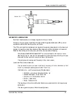
Page 16: ...age occurs from contaminated air or lack of lubrication When the Model 204B BEVELMASTER is operated in the vertical position cutting head up it should be turned upside down and the chips and or other debris removed after each bevel has been completed Tool life may be severely shortened unless chips and or other debris that have been deposited on the cutting head during the machining operations are...

Page 17: ...odel 204B BEVELMASTER is to be left idle for 24 hours or more after being run on wet air it is advisable to squirt oil directly into the air motor inlet and run the motor for two 2 to three 3 seconds This will prevent rusting and freezing of the rotor vanes Lubricant Recommendations The air motor requires a Class 2 lubricant viscosity of 100 to 200 SSU at 100 F 38 C minimum aniline point of 200 F ...

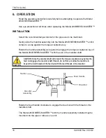
Page 18: ... the mandrel assembly as required to engage the torque acceptance key of the Model 204B BEVELMASTER with the slot in the mandrel shaft CAUTION CAUTION Since the mandrel shaft will contact the torque acceptance key before the feed nut engages the mandrel shaft threads do not force or allow the machine to impact the lead threads of the feed nut with the lead threads of the mandrel Tool Bit Mandrel A...

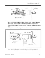
Page 19: ...operation the mandrel must be installed beyond the final preparation location Tighten the draw nut to force the jaw blocks out to the inside diameter of the pipe or tube Verify a clearance of 1 8 3 mm minimum between the tool bit and the pipe face Feed Handle Draw Nut Tool Bit 1 8 3 mm Clearance Pipe Mandrel Clearance Select the tool bit s required to machine the pipe to the configuration desired ...

Page 20: ... Bit Beveling Cam Adjustment Cutting Head Rotation Insert the tool bit s into the slot s in the cutting head Make sure that there is a clearance between the tool bit s and the mandrel Tighten the setscrews to secure the tool bit in the tool bit slot Adjust the bevel tool bit radially to control the land width Adjust the cam to alter the width of the land with the facing tool bit Attach the proper ...

Page 21: ...onnection Rotate the feed handle clockwise to bring the tool bit s and pipe closer together WARNING WARNING Do not override the dead man switch on this unit Locking down obstructing or in any way defeating the dead man switch on this unit may result in serious injury CAUTION CAUTION The actual machining operation will begin when the first tool bit contacts the pipe Flow Control Valve Deadman Switc...

Page 22: ...l the end of the pipe is completely machined Discontinue feed and allow the head to rotate one 1 to three 3 revolutions to improve finish of the prep surface Release the air motor trigger to stop the head rotation Rotate the feed handle counterclockwise to separate the tool bit s from the pipe Rotate the feed handle counterclockwise until the tool bit to pipe relationship is the same as described ...

Page 23: ...ts BASIC FEED RECOMMENDATION Use very light feed for initial beveling or until a continuous cut is established This is very important for longer tool bit life when cutting through flame cut or out of square pipe ends Use adequate feed 003 to 006 08mm to 15mm per revolution thereafter to establish a continuous chip cut If the feed is too light only light stringer chips will be removed If the feed i...

Page 24: ...TRI TOOL INC 92 0699 Rev 060412 22 8 JAW BLOCKS AND RAMP SETS Mandrel Assembly Block Ramp STEEL JAW BLOCKS AND RAMPS Used with Mandrel Assembly P N 06 0419 ...

Page 25: ...to 41 4 mm 1 560 to 2 000 39 6 mm to 50 8 mm 1 930 to 2 390 49 0 mm to 60 7 mm 2 320 to 2 780 58 9 mm to 70 6 mm 2 710 to 3 160 68 8 mm to 80 3 mm 3 090 to 3 550 78 5 mm to 90 2 mm Mounting ID Ramp and Block Combination STEEL JAW BLOCK AND RAMP PROFILES STANDARD MANDREL ...

Page 26: ...TRI TOOL INC 92 0699 Rev 060412 24 3 480 to 3 940 88 4 mm to 100 1 mm 3 870 to 4 330 98 3 mm to 110 0 mm Mounting ID Ramp and Block Combination STEEL JAW BLOCK AND RAMP PROFILES STANDARD MANDREL ...

Page 27: ...9 Rev 060412 25 BUTT PLATE SPRING AND RAMP BUTT PLATE SPRING AND RAMP Mandrel Assembly Mandrel Sleeve Spring Butt Plate Ramp Spring Mandrel Assembly Ramp Used with Mandrel Assembly P N 06 0413 Used with Mandrel Assembly P N 06 0414 ...

Page 28: ... or Beveling Range Wall Tube Tool Bit Thickness Material P N 1 1 4 ID thru 3 pipe 31 8 mm ID thru 88 9 mm OD 531 13 5 mm CS Durabit 7 3 thru 4 pipe 88 9 mm ID thru 114 3 mm OD 531 13 5 mm SS 99 3712 3 thru 4 pipe 88 9 mm ID thru 114 3 mm OD 531 13 5 mm CS 99 3711 1 1 4 ID thru 3 pipe 31 8 mm ID thru 88 9 mm OD 531 13 5 mm SS 99 3111 ...

Page 29: ...Model 204B BEVELMASTER 92 0699 Rev 060412 27 TOOL BIT BEVELING AND FACING Cutting Head Facing Tool Bit Cutting Edge Pipe Tool Bit Beveling ...

Page 30: ...TRI TOOL INC 92 0699 Rev 060412 28 TOOL BIT FACING LAND Tool Bit Facing Land Pipe Cutting Edge Cutting Head ...

Page 31: ...Model 204B BEVELMASTER 92 0699 Rev 060412 29 TOOL BIT ID CHAMFER Cutting Head Pipe Cutting Edge Tool Bit ID Chamfer ...

Page 32: ...matter on the pipe or tube which is dulling the tool bit at the start of the cut The tool bit is incorrect for the material being cut Problem The surface finish is rough The tool bit is dull chipped etc Metal buildup on the cutting edge of the tool bit is creating a false cutting edge Cutting fluid is required Problem There is a loss of air power The air supply pressure is too low The air filter i...

Page 33: ...ndrel Assembly P N 06 0413 610 to 1 00 Range 4 Mandrel Assembly P N 06 0414 1 00 to 1 25 Range 5 Mandrel Kit Elbow P N 05 0293 6 Squaring Plate Kit Elbow Mandrel P N 05 1330 7 Flange Facer Kit P N 05 0292 8 Pointer Kit Elbow Mandrel 204B P N 05 0316 9 Indicator Kit Dial P N 05 0317 10 Adjustable Pin Kit Elbow Mandrel P N 05 0355 A portable Air Caddy FRL is required to protect the warranty on all T...

Page 34: ...TRI TOOL INC 92 0699 Rev 060412 32 12 ILLUSTRATED PARTS BREAKDOWN MODEL 204B BEVELMASTER SUB ASSEMBLY P N 02 2222 1 10 3 5 7 8 9 11 14 19 16 27 28 31 A 10 9 ...

Page 35: ...Model 204B BEVELMASTER 92 0699 Rev 060412 33 MODEL 204B BEVELMASTER SUB ASSEMBLY P N 02 2222 Con t 2 4 6 12 13 15 18 20 21 22 23 24 25 26 29 30 17 A ...

Page 36: ... 2 11 29 0345 BEARING BALL 1 12 30 0309 RING RETAINING EXTERNAL 1 13 30 0411 RING RETAINING EXTERNAL 1 14 30 2358 RING RETAINING INTERNAL 1 15 30 2359 SHIM 1 16 31 0103 KEY SQUARE ROUND ENDS 1 17 31 0155 KEY SQUARE 1 18 32 0081 PIN DOWEL 3 16 DIA X 3 4 2 19 32 0493 PIN DOWEL 1 8 DIA X 7 8 1 20 33 0030 SCREW CAP 10 24 X 3 4 1 21 33 0047 SCREW CAP 1 4 20 X 2 1 4 4 22 34 0236 WASHER THRUST 1 23 34 03...

Page 37: ...BEVEL PINION 1 28 39 0755 GEAR BEVEL 1 29 40 0227 SPRING WAVE 1 30 45 0248 BUSHING FEED ADAPTER 1 31 54 0375 FITTING GREASE 1 NOT SHOWN 05 1327 WRENCH KIT 204B 36 0004 WRENCH L 7 64 HEX 1 36 0006 WRENCH L 9 64 HEX 1 36 0007 WRENCH L 5 32 HEX 1 36 0010 WRENCH L 1 4 HEX 1 36 0018 WRENCH T 1 8 HEX 1 36 0020 WRENCH T 5 32 HEX 1 36 0076 WRENCH COMBINATION 9 16 1 86 0214 CARRYING CASE 1 ...

Page 38: ...12 36 MOTOR ASSEMBLY AIR P N 57 0224 1 53 0046 VALVE FLOW CONTROL 1 2 54 0126 COUPLING MALE QD 1 3 54 0201 CAP YELLOW 1 4 57 0223 MOTOR INLINE AIR 1 Parts List Motor Assembly Air P N 57 0224 1 2 3 4 Item Part No No Description Qty ...

Page 39: ...039 MOTOR MOD ELECTRIC 220V 1 2 27 0357 ADAPTER MOTOR 1 3 39 0568 GEAR DRIVE 1 4 29 0182 BEARING BALL 1 2 X 1 1 8 X 3 8 1 5 91 0545 GEAR ASSEMBLY 1 6 33 0039 SCREW CAP 1 4 20 X 5 8 2 7 44 0441 SPACER 1 58 0147 MOTOR ASSEMBLY 110V 1 Parts List Electric Motor Assembly 220V 1 2 3 4 5 7 6 Item Part No No Description Qty ...

Page 40: ...038 MOTOR MOD ELECTRIC 110V 1 2 27 0357 ADAPTER MOTOR 1 3 39 0568 GEAR DRIVE 1 4 29 0182 BEARING BALL 1 2 X 1 1 8 X 3 8 1 5 91 0545 GEAR ASSEMBLY 1 6 33 0039 SCREW CAP 1 4 20 X 5 8 2 7 44 0441 SPACER 1 Parts List Electric Motor Assembly 110V Item Part No No Description Qty ...

Page 41: ...1 2 3 4 5 7 6 8 1 21 0475 HEAD 4 0 DIA 1 2 28 0249 SEAL OIL 1 3 33 0057 SCREW CAP 5 16 18 X 1 1 4 3 4 33 0514 SCREW SET 5 16 18 X 3 8 CUP PT 1 5 33 0517 SCREW SET 5 16 18 X 5 8 CUP PT 6 6 33 0518 SCREW SET 5 16 18 X 3 4 CUP PT 3 7 33 0996 SCREW SET 5 16 18 X 1 2 HDOG 1 8 62 0104 CAM FACING BIT 1 Item Part No No Description Qty ...

Page 42: ...64 PLATE BUTT 2 1 4 33 0477 SCREW SET 8 32 X 3 16 CUP PT 1 33 0478 SCREW SET 8 32 X 1 4 CUP PT 1 5 35 0523 NUT DRAW ROD 3 8 16 1 6 40 0130 SPRING FLAT 1 40 0136 SPRING FLAT 1 7 46 0437 SLEEVE MANDREL 1 8 48 0596 BLOCK RAMP 1 3 48 0597 BLOCK RAMP 2 3 Parts List Mandrel Assembly P N 06 0413 1 2 3 4 5 7 6 8 Item Part No No Description Qty ...

Page 43: ...Parts List Mandrel Assembly P N 06 0414 Item Part No No Description Qty 1 13 0426 MANDREL 1 2 23 0297 ROD DRAW 1 3 24 1462 PLATE BUTT 1 4 33 0489 SCREW SET 10 24 X 5 16 CUP PT 1 5 35 0523 NUT DRAW ROD 3 8 16 1 6 40 0108 SPRING EXTENSION 1 7 48 0976 BLOCK RAMP 3 1 2 3 4 5 7 6 ...

Page 44: ... Description Qty 1 08 XXXX BLOCK JAW Ref the Jaw Blocks section REF 2 13 0424 MANDREL 1 3 23 0295 ROD DRAW 1 4 24 1384 PLATE BUTT 1 5 33 0490 SCREW SET 10 24 X 3 8 CUP PT 1 6 35 0523 NUT DRAW ROD 3 8 16 1 7 40 0001 SPRING EXTENSION 5 8 48 0964 BLOCK RAMP 1 3 48 0965 BLOCK RAMP 2 3 48 0966 BLOCK RAMP 3 3 1 2 3 4 5 7 6 8 ...

Page 45: ......
Page 46: ...any safety triggers SHOCK HAZARD Ensure that the equipment is properly installed and grounded Ensure that the equipment is not damaged and that the power cord is intact Tool bits are sharp and can cause serious injury Do not defeat or modify safety features Disconnect power sources before servicing or moving the equipment Remove all loose articles of clothing and jewelry before operating the equip...

Reviews: