TOC1408NUENa_1214
3/4
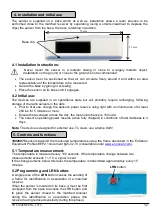
The sensor is supplied on a base which as well as installation allows a learn process to be
performed close to the matched receiver by separating (using a small screwdriver to depress the
clips) the sensor from the base; the base remaining in position.
Base clip
4.1 Installation instructions:
Never mount the sensor in a metallic casing or close to a largely metallic object.
Installation on the ground or close to the ground is not recommended
The sensor must be positioned so that air can circulate freely around it and within an area
representative of the temperature to be measured.
Secure the base by gluing or screwing.
Place the sensor on its base until it engages.
4.2 Initial use:
The devices are supplied in an operational state but will probably require recharging, following
storage of the radio sensors in the dark.
Prior to first use, charge the sensor's power reserve using light with an illuminance of at least
200 lux for 5 minutes or more.
Ensure that averaged across the day, the mean illuminance is 100 lux/d.
The sensor's operating power reserve (when fully charged) in conditions of total darkness is 4
days.
Note:
The device is designed for external use. To clean, use a damp cloth!
10020076
sensors transmit the measured temperatures using the frame described in the EnOcean
Equipment Profiles EEP2.1 document §A5-02-13 (consultable under
5.1 Temperature measurement:
The temperature is measured every 100 seconds. If the temperature change between two
measurements e/-1°C, a signal is sent.
If the change remains below this level, the temperature is transmitted approximately every 15
minutes.
5.2 Programming and LRN button:
A single press of the
LRN
button causes the sending of
a frame for identification or association of a matched
receiver.
When the sensor is located on its base, it must be first
unclipped from the base to access the LRN button and
to place the sensor closed to the matched receiver
during the identification or association phase (the
receiver having reduced sensitivity during this phase).
78 mm
25 mm
LRN
button
4. Installation and initial use
5. Controls and functions
ion and initial use


