Cold water
inlet
4
3
3
6
7
8
1
To dishwasher if
permitted by codes
2
2
9
3*
6" Heat trap
3
U-Tube
assembly
6" Heat trap
8
1
2
To dishwasher if
permitted by codes
3*
Cold water
inlet
4
3
3
6
9
U-Tube
assembly
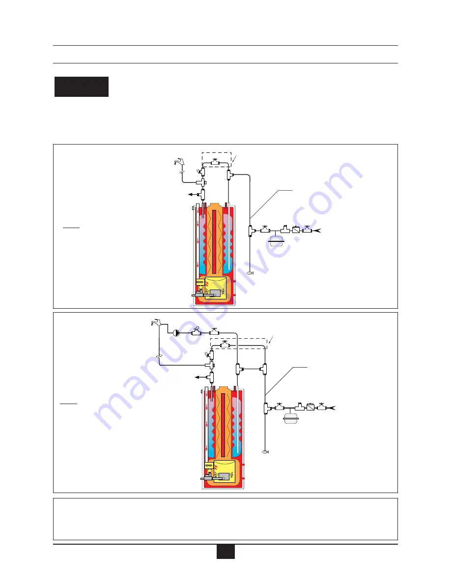
Fig. 8: G Model with mixing
valve and recirculation
Fig. 7: G Model with mixing
valve without recirculation
1. Mixing valve
2. Flow check valve
3. Shut off valve
4. Backflow preventer or pressure reducing valve
6. Thermal expansion tank
7. Circulator (controlled by aquastat)
8. Domestic drain valve
9. Vacuum breaker (if code permitting)
Note: All shut off valves
shown in this figure must be
shut when siphon draining
the combination heater
Note: All shut off valves
shown in this figure must be
closed when siphon draining
the combination heater
* Re-attach valve handle when draining
inner tank.
* Re-attach valve handle when
draining inner tank.
11
Do not use automotive, ethylene glycol or any
undiluted or petroleum-based antifreeze.
This can cause severe personal injury, death
or substantial property damage.
•
Any water conditioning system must be
installed and maintained in accordance
with manufacturer’s specifications.
WARNING
INSTALLATION


