


Instinct
Condensate Pan Replacement
7
jacket panel.
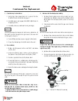
2. Push and twist the flue tube into the flue tube seat.
Ensure the rubber seal is in place in the flue tube
seat. Orient the flue tube so that the flue sensor is
facing forward.
3. Ensure the rubber seal is in place in the top of the
flue tube. Reinstall the vent outlet adapter, pushing
it down firmly to secure it to the flue tube.
WARNING
!
Ensure the gasket is in place before reassembly. Fail-
ure to do so can result death, serious injury or sub-
stantial property damage.
4. Reinstall the four screws to secure the vent adapter.
WARNING
!
Ensure the screws are in firmly installed prior to start-
ing the boiler. Failure to do so can result death, seri-
ous injury or substantial property damage.
5. Reconnect the vent piping to the vent outlet
adapter. Tighten the banding clamp with a flat-
head screwdriver to secure the vent piping to the
adapter.
WARNING
!
Ensure the venting is tight and secure prior to start up.
Failure to do so can result death, serious injury or sub-
stantial property damage.
6. Reinstall the flue temperature sensor by pushing it
into the rubber boot.
7. Plug in the molex plug into the flue sensor.
11a. Installation of Condensate Trap (Combi Models)
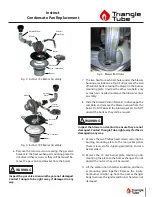
1. Install the retaining nut and both seals onto the
drain nipple. See Fig. 10.
2. Push the condensate trap onto the condensate
nipple as far as it will go.
3. Tighten the retaining nut to the condensate trap to
secure the condensate trap.
4. Pull the condensate drain hose out the bottom of
the boiler.
5. Install the access panel and tighten the three Phil-
lips screw.
11b. Installation of Condensate Trap (Solo Models)
1. Push the retaining nut and both seals onto the
drain nipple. See Fig. 10.
2. Push the condensate trap onto the drain nipple as
far as it will go.
3. Tighten the retaining nut to the condensate trap to
secure the condensate trap.
4. Pinch and install the retention clip to secure the
condensate trap.
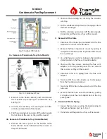
12. Install Burner Assembly
1. Align the burner/combustion chamber insulation
with the gas valve facing the front of the boiler. See
Fig. 1, Fig. 2, Fig. 3.
2. Align the bolt holes in the insulation and burner
mounting plate. Carefully install the assembly into
the heat exchanger, pushing the heat exchanger
studs through the bolt holes.
WARNING
!
Ensure the burner/gas valve/igniter are not damaged.
Contact Triangle Tube right away if any item is dam-
aged in any way.
3. Reinstall the burner plate nuts. Make all nuts hand
tight. Once all nuts are finger tight, torque all nuts
to 44-53 in-lbs in a star pattern.
4. Place the blower gasket in place onto the burner
mounting plate.
5. Place the blower/venturi assembly onto the mount-
ing plate by sliding the two slotted holes onto the
two partially installed bolts. Tighten all four 8mm


