background image

1

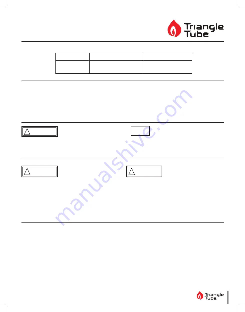
Instinct FSB (Floor Standing Boiler) 

HMI (Human Machine Interface) Removal

WARNING

!

Indicates a potentially hazardous situation 

which, if ignored, can result in serious  injury or 

substantial property damage.

NOTICE

Indicates special instructions on installation, operation 

or maintenance, which are important to equipment 

but not related to personal injury hazards.

WARNING

!

For your safety, turn off electrical power supply 

at service panel and allow unit to cool before pro-

ceeding to avoid possible electrical shock and 

scald hazard.  Failure to do so can cause severe 

personal injury or death.

WARNING

!

Failure to follow instructions below can result in 

severe personal injury or damage if ignored.

Instructions are for a qualified installer/

service technician only.

Read all instructions before proceeding.

Follow instructions in proper order.

UIN 232788 A01

2021-51 Instinct FSB HMI Replacement

Revision Date:  02/2022

Kit Part Number

Description

Model

INSRKIT128

HMI Replacement

Instinct Floor Standing 

Models

Each Kit Includes:

• Display Module with cover

Recommended Tools:

• Pozidriv Screwdriver

• Flat Head Screwdriver

Summary of Contents for Instinct FSB

Page 1: ...ool before pro ceeding to avoid possible electrical shock and scald hazard Failure to do so can cause severe personal injury or death WARNING Failure to follow instructions below can result in severe...

Page 2: ...dule s Use Table 1 to record the existing settings Do not revise any settings when recording settings 1 To access the Installer screen touching simultane ously the up and down soft keys for 3 seconds...

Page 3: ...Enabled Switch 186 F 140 F 6 F 46 F Fig 7 DHW Settings 9 Press the DOWN button to highlight the Boiler Settings icon if present icon then press the OK button 10 Press the UP and DOWN buttons to scroll...

Page 4: ...screws 1 Locate and undo the 2 M6 access screws Fig 8 Access Screws 2 Raise the HMI Pod 3 Disconnect the high and low voltage connectors Fig 9 High and Low Voltage Connectors 4 Rotate the HMI Pod down...

Page 5: ...2 Remove the Wi Fi Module 21 and remove the 8 way harness from the aperture Keep the harness plugged into the Wi Fi Module 21 Reset Power Fig 13 8 way harness 5 Fitting Wi Fi Module on replacement HMI...

Page 6: ...pliance Setting 3 The required code is written on the data plate located at the side of the boiler Use the code for the gas type either Natural Gas or Propane 4 Increase decrease the value from 0 to 9...

Page 7: ...reeze Protection Enabled Frost Protection Setpoint 22 F 30 C 22 F 30 C 50 F 10 C Parallel Shift Value 0 F 0 C 0 F 0 C 144 F 80 C CH Call Blocking 2 Minutes 0 Minutes 30 Minutes DOMESTIC SETTING SOLO F...

Page 8: ...dbus Address 0 BCST 0 BCST 247 Flex Relay 1 CH CH1 Flex Relay 2 DHW DHW Flex Relay 3 P3 CH1 CH2 DHW Flex Relay 4 ERR ERROR Flex Relay 5 Flame FLAME Flex Relay 6 P4 CH2 Error Relay On Lockout Blocking...

Reviews: