
2
Instinct FSB (Floor Standing Boiler)
HMI (Human Machine Interface) Removal
1. Preliminary Instructions
1. Verify that the
replacement kit is correct for the
model of boiler.
2. Carefully open and unpack the PARTS BOX from its
shipping carton.
3. Carefully remove and check for any damage.
NOTICE
Installing damaged
equipment will cause malfunction of the
boiler. Contact Triangle Tube right away if the display mod-
ule is damaged in any way.
4. Close the manual gas shut off valve to the unit.
5. Turn the power to the boiler off.
2. Save Settings
NOTICE
Prior to replacing the control module and/or display module, it
is important to access and document the boiler’s settings. This
will ensure any settings revised from factory defaults are trans-
ferred to the new module(s). Use Table 1 to record the existing
settings. Do not revise any settings when recording settings.
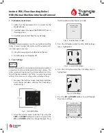
1. To access the Installer screen, touching simultane-
ously the up and down soft keys for 3 seconds as
shown in Fig. 1.
Fig. 1: Installer Button
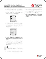
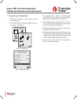
2. Enter the installer access code “054” by using the
LEFT
and
RIGHT
buttons to select a digit and the
UP
and
DOWN
buttons to change the digit. Press
the OK button to enter the access code.
ENTER INSTALLER
ACCESS CODE
[0]XX
Fig. 2: Installer Access Code
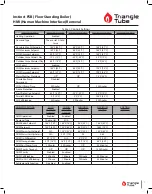
3. Press the OK button while the CH & DHW Settings
icon is highlighted.
CH & DHW Settings
Fig. 3: CH & DHW Settings
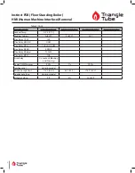
4. Press the OK button while the CH Settings icon is
highlighted.
CH Settings
Fig. 4: CH Settings
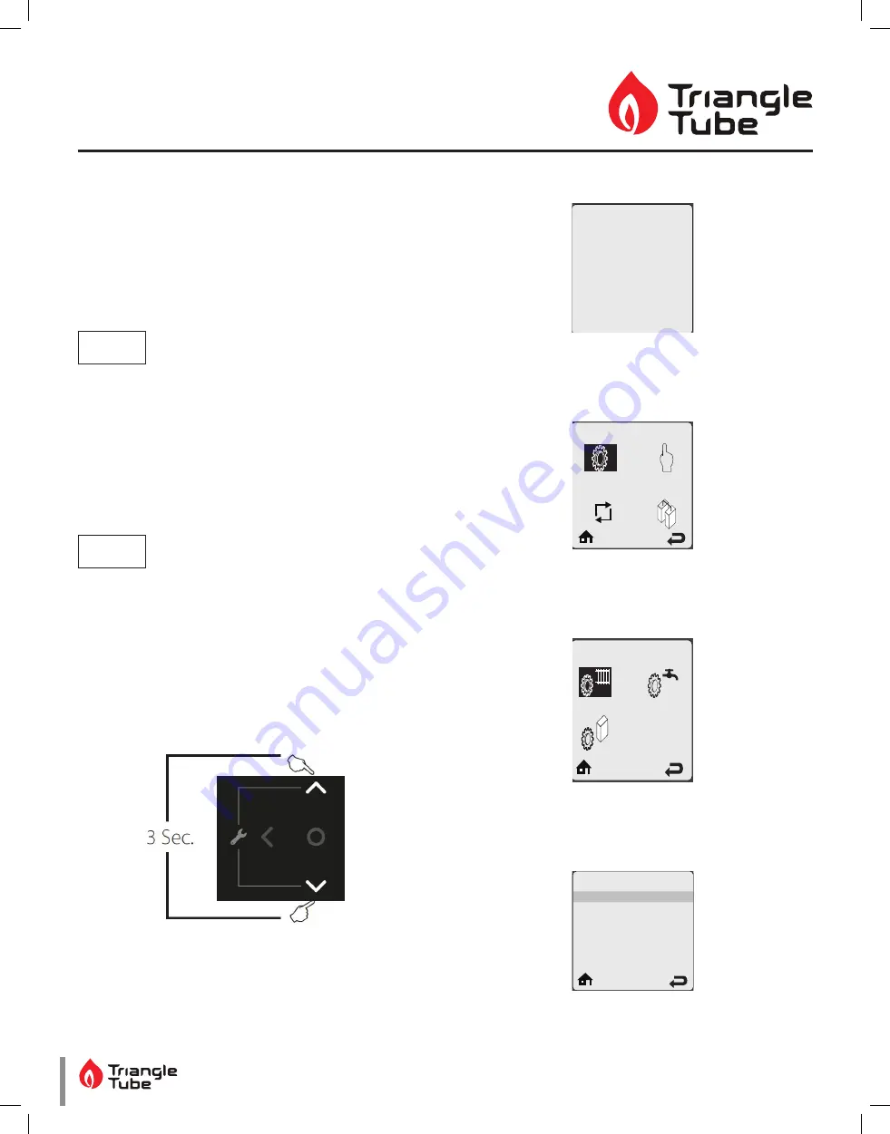
5. Press the
UP
and
DOWN
buttons to scroll through
the various settings.
Heating Settings
Heating Operation
Demand
Absolute Max CH Setpoint
CH1 Maximum Setpoint
CH1 Minimum Setpoint
Reset Curve Coldest Day
Enabled
Switch & Setpoint
188ºF
180ºF
120ºF
0ºF
Fig. 5: Heating Settings


