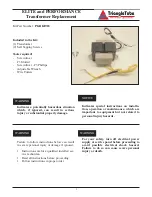

ELITE and PERFORMANCE
Transformer Replacement
Removal of the Transformer
1. Disconnect electrical power supply to the
Combination Heater
2. Disengage the top jacket panel from the side
jacket panels using an upward force along the
front edge of the top panel.
3. Remove the front jacket panel by placing a slot-
ted screwdriver between the front panel and the
side jacket panels and using a twist motion.
Use extreme care as not to damage or scratch
the jacket panels with the screwdriver when
removing the front jacket panel.
4. Remove the (4) locking pins along the corners
of the front control panel. On the PERFOR-
MANCE units remove the air inlet mounting
screw along the front edge of the control panel.
5. Lay the front control panel forward to expose
the transformer and control wiring.
6. Using the wire cutters remove any wire ties
along the existing Transformer wiring.
7. Use a #3 slotted screwdriver to disengage the 24
volt wiring of the Transformer from terminals 5
and 6.
8. Use a #3 slotted screwdriver to disengage the
120 volt wiring of the Transformer from termi-
nals 1 and 2.
9. Use a #3 Phillips screwdriver to remove the
mounting screws on the existing Transformer and
remove the Transformer from the control panel.
Installation of the Transformer
1. Mount the new Transformer onto the control
panel using (2) self tapping screws.
2. Attach the 24 volt wire leads of the Transformer
to terminals 5 and 6. Ensure all leads are
securely insert into the terminals and the termi-
nals are completely tighten. Trim lead lengths to
accommodate installation as needed.
3. Attach the 120 volt wire leads to terminals 1
and 2. The black lead should be attached to ter-
minal 1 and the white lead to terminal 2. Ensure
all leads are securely insert into the terminals
and the terminals are completely tighten. Trim
lead lengths to accommodate installation as
needed.
If the Transformer wire leads are cut to
length, DO NOT strip the wire end more
than 1/4”. To prevent a potential.
4. Re-install the front control panel using the lock-
ing pins to secure the panel into place.
To prevent potential damage to the unit
and/or electrical shock hazard ensure the
capillary tubes of the operating aquastats are
tucked up under the front control panels and
not lying across any wire terminals.
5. Reattach the top jacket panel by aligning and
engaging the panel onto the locking pins.
6. Reattach the front jacket panel by inserting the
lower tabs into the side jacket panels and then
engaging the upper locking pins.
7. Reconnect the power supply and return the unit
to service.
WARNING
WARNING
NOTICE
2
2002-62 Elite &Performance Transformer Replacement
07/02


