background image

Prestige SOLO 399

Burner Mounting Plate Kit

1

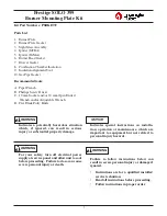
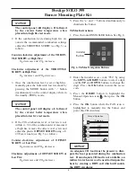
Kit Part Numbers: PSRKIT39

Parts List 

1. Burner Plate

2. Burner Plate Gasket

3. Sight Glass Assembly

4. Igniter (MCBA)

5. Igniter (TriMax)

6. Burner Head Gasket

7. Blower Gasket

8. Combustion Chamber Insulation

9. Insulation Alignment Tool

10. Gas Pipe Gasket

Recommended tools:

A. Pipe Wrench.

B. Phillips Screw Driver.

C. 10 mm Socket and/or 10 mm Open Ended

Wrench and/or Adjustable Wrench.

D. Flat Blade Putty Knife.

Indicates  a  potentially  hazardous  situation

which,  if  ignored,  can  result  in  serious

injury or substantial property damage.

For  your  safety,  turn  off  electrical  power

supply at service panel  and allow unit to cool

before proceeding.  Failure to do so can cause

severe personal injury or death.  

Indicates  special  instructions  on  installa-

tion,  operation  or  maintenance,  which  are

important  to  equipment  but  not  related  to

personal injury hazards.

Failure  to  follow  instructions  below  can

result in severe personal injury or damage if

ignored.
• Instructions are for a qualified installer/

service technician.

• Read all instructions before proceeding.

• Follow instructions in proper order.

WARNING

WARNING

NOTICE

WARNING

Summary of Contents for PSRKIT39

Page 1: ...rdous situation which if ignored can result in serious injury or substantial property damage For your safety turn off electrical power supply at service panel and allow unit to cool before proceeding...

Page 2: ...ors from the blower and remove the blower retaining nuts Remove the blower with venturi and gas valve from the unit 11 Remove the 10 mm nuts and remove the burn er mounting plate assembly from the hea...

Page 3: ...g nuts are in place use a wrench to tighten using an alternating pattern until the gasket is slightly compressed See Table 2 page 7 for torque specifications 21 Re assemble the blower onto the burner...

Page 4: ...is operating at optimum conditions The combustion testing and adjustments must be performed by a qualified installer service agency or the gas supplier All com bustion measurements must be perform wit...

Page 5: ...wrench see Fig 5 as follows Counter clockwise adjustment of OFFSET SCREW at Low Fire O2 increases and CO2 decreases Clockwise adjustment of OFFSET SCREW at Low Fire O2 decreases and CO2 increases 5 P...

Page 6: ...mbustion level is set at high fire manually place the boiler into low fire mode by pressing the LEFT button to adjust firing rate down to 1 low fire 8 If the CO2 combustion level at low fire is not wi...

Page 7: ...for latest recommendations 2 Wear long sleeved loose fitting clothing gloves and eyes protection 3 Assure adequate ventilation 4 Wash with soap and water after contact 5 Wash potentially contaminated...

Reviews: