The control panel will display a H followed
by the current boiler temperature when
placed into high fire test mode.
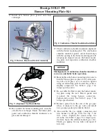
2. If the combustion levels during high fire are
outside the recommended combustion settings
adjust the THROTTLE SCREW (see Fig. 5) as
follows:
Counter-clockwise adjustment of the THROT-
TLE SCREW at High Fire:
O2 decreases and C02 increases
Clockwise adjustment of the THROTTLE
SCREW at High Fire:
O2 increases and CO2 decreases
3. Once the combustion level is set at high fire,
manually place the boiler into low fire mode by
pressing the MODE button with “-” button
simultaneously on the control display while in
the standby (STBY) mode.
The control panel will display a L followed
by the current boiler temperature when
placed into low fire test mode.
4. If the CO
2
combustion level at low fire is not
/- 0.2 of the combustion level measured
at high fire, remove the offset cover screw and
adjust the plastic
OFFSET SCREW
using a T-
40 Torx wrench (see Fig. 5) as follows:
Counter-clockwise adjustment of OFFSET
SCREW at Low Fire:
O2 increases and CO2 decreases
Clockwise adjustment of OFFSET SCREW at
Low Fire:
O2 decreases and CO2 increases
5. Press the “+” and “-” buttons simultaneously to
shutdown the burner.
TriMax Instructions
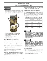
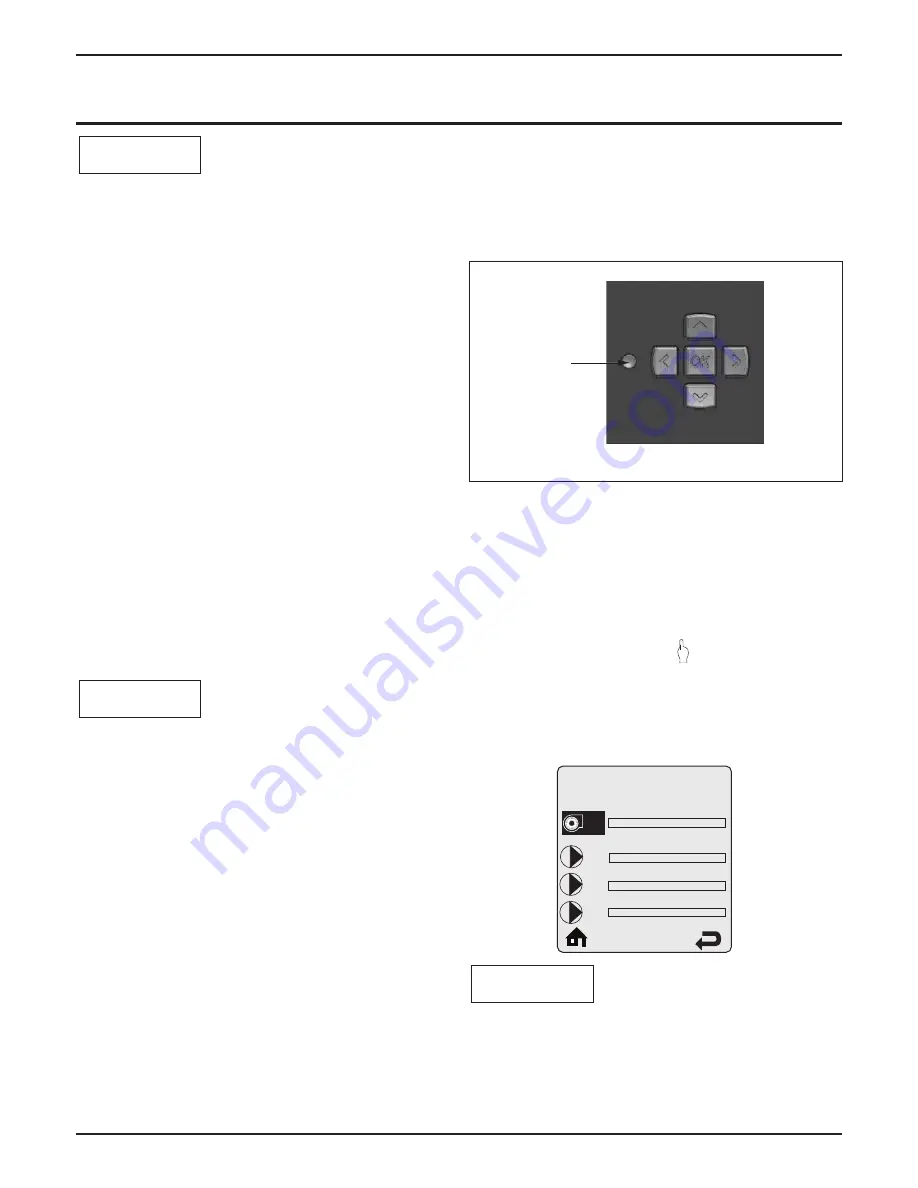
1. Press the round INSTALLER button. See Fig. 6.
2. Enter the installer access code “054” by using
the
LEFT
and
RIGHT
buttons to select a digit
and the
UP
and
DOWN
buttons to change the
digit. Press the
OK
button to enter the access
code.
3. Press the
RIGHT
button to highlight the
Manual Operation icon
then press the
OK
button.
4. Press the
OK
button while the FAN icon is
highlighted to manually fire the burner and
power the CH circulator.
An adequate CH load must be present to dissi-
pate the heat generated during the combustion
test. If an adequate CH load is not available, an
indirect water heater can be used to dissipate the
heat by creating a DHW call which will enable
the DHW circulator.
NOTICE
NOTICE
NOTICE
Prestige SOLO 399
Burner Mounting Plate Kit
5
Installer
Button
Fig. 6: TriMax Navigation Buttons
Manual Operation
Released
Off
Off
Off
CH
CH1
FAN
DHW
SYS
CH2


