Prestige SOLO 110 and EXCELLENCE
Natural to LP Conversion
3
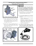
15. Using a T-25 Torx wrench remove the three
screws attaching the gas valve to the venturi.
Note the orientation of the gas valve to the ven-
turi for reference later when the gas valve is
reassembled to the venturi.
16. Seat the brass orifice into the black gasket on
the gas valve. The black rubber orifice gasket
must remain attached to the gas valve as it will
hold the orifice. See Fig. 3.
Failure to retain the rubber orifice gasket on the gas
valve will cause an improper seal between the gas
valve and the venturi resulting in a potential gas
leak. Any potential gas leakage may result in death,
serious injury or substantial property damage.
17. Reassemble the gas valve onto the venturi using
the three T-25 Torx screws. Ensure the gas valve
is orientated with the venturi correctly.
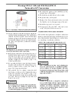
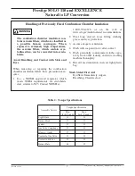
18. Use the included alignment tool to install the
new combustion chamber insulation in the heat
exchanger.
- Insert the alignment tool into the igniter
opening as shown in Fig. 4.
- Install the new combustion chamber insula-
tion in the heat exchanger so that the align-
ment tool goes over the correct heat
exchanger stud as shown in Fig. 5.
- Remove the alignment tool.
19. Re-assemble the burner mounting plate assembly
onto the heat exchanger. Ensure the burner plate
gasket and combustion chamber insulation is in
place and not damaged, replace gasket if necessary.
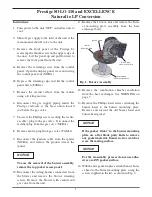
WARNING
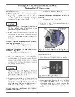
Burner Head
Burner Mounting
Plate
Burner Head
Gasket
Fig. 2: Burner Head and Gasket Assembly
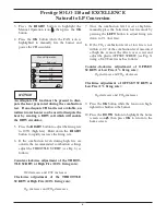
Gas Valve
Blower
Venturi
Throttle
Screw
Insert Brass
Propane Orifice.
Maintain Black Gasket
on Gas Valve
Fig. 3: Venturi/Gas Valve Assembly
Fig. 4: Alignment Tool Installation


