5
CHAPTER
2
CHAPTER 2 - INSTALLATION - PIPING
• If copper pipe is used for domestic water connections,
first solder pipe to a threaded adapter and then screw
adapter into cold water inlet on top of water heater.
Inlet connection contains an internal plastic dip tube
which can be damaged by heat from soldering.
Do not apply heat to the cold water inlet when
making sweat connections to water heater.
Sweat tubing to adapter before fitting adapter
to cold water inlet of heater. It is imperative that
no heat be applied to the cold water inlet, as it
contains a non metallic dip tube.
• When the water supply pressure is higher than 70
psig, it is recommended to install a pressure reduc-
ing valve on cold water supply line to prevent wa-
ter loss through T&P relief valve.
• If the water heater will replace a tankless coil in the
boiler, disconnect the piping to coil and allow the
water to drain from coil. Do not plug the tankless coil.
Plugging tankless coil inlet and outlet will re-
sult in substantial property damage, serious
injury, or death.
2.9. Thermostatic Mixing Valve
• It is recommended to install an optional mixing
valve on the domestic hot water outlet.
• Mixing valve must comply with ASSE 1017
NOTICE
DANGER
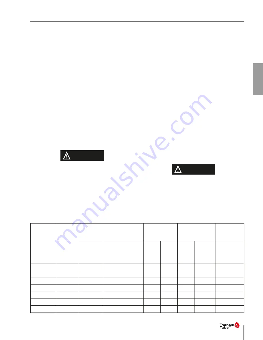
Table 1 - Piping dimensions
Water
Heater
Model
Connections (inches)
Recirculation Dip
Tube
Draining Dip Tube
Recommend-
ed Minimum
Boiler Piping
Domestic
Water
Inlet/Outlet
(NPT)
Boiler Water
Supply/
Return
(NPSC)
Auxiliary Connection
(NPSC)
Length
(Inches)
Diam-
eter
(Inches)
Length
(Inches)
Diameter
(Inches)
Diameter
(Inches)
SMART 30
3/4
1
3/4
34
3/4
34
3/4
1
SMART 40
3/4
1
3/4
43
3/4
43
3/4
1
SMART 50
3/4
1 1/4
3/4
25
3/4
52
3/4
1
SMART 60
3/4
1 1/4
3/4
34
3/4
62
3/4
1 1/4
SMART 80
1 1/2
1 1/2
1 1/2
25
1 1/2
48
1 1/2
1 1/4
SMART 100
1 1/2
1 1/2
1 1/2
32
1 1/2
61
1 1/2
1 1/2
SMART 120
1 1/2
2
1 1/2
32
1 1/2
61
1 1/2
1 1/2
2.11. Multiple Water Heater Systems
• Parallel Pipe Recirculation Systems - Manifold recircu-
lation return to all water heaters.
• Series Piped Systems - Piped return to the leading
(cold water inlet) water heater.
• Install an automatic mixing valve either at the hot wa-
ter outlet of water heater or each hot water faucet.
Failure to install automatic mixing valve
where recommended will result in serious in-
jury, or death.
DANGER
2.10. Recirculation Piping.
• T&P relief valve must be installed in run (straight
through leg) of tee located at domestic hot water
outlet of water heater.
• It is recommended that the recirculation dip tube
be installed in auxiliary connection using a close
nipple assembly as shown in
Fig. 3 on page 7.
See
Table 1
below for diameter and length of dip
tube.
• A stainless steel or bronze circulator is required on
potable water systems.
• Install automatic mixing valve either at the hot wa-
ter outlet of water heater or each hot water faucet
Summary of Contents for SMART Series
Page 2: ...INTENTIONALLY LEFT BLANK ...
Page 6: ...INTENTIONALLY LEFT BLANK ...
Page 22: ...INTENTIONALLY LEFT BLANK ...
Page 28: ...INTENTIONALLY LEFT BLANK ...
Page 37: ......
Page 38: ......
Page 39: ......


