background image

FMS-1655L

Due to continuous improvement, Triatek reserves the right to change product specifications without notice.

GENERAL

Overview

Triatek reserves the right to change product specifications without notice.

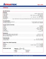
The Triatek FMS-1655L Room Pressure 

Controller is an ultra-sensitive instrument 

used to control and/or monitor air pressure 

in hospital rooms, labs, and clean rooms. It 

is capable of measuring and displaying air 

pressures down to 0.0001” wc. 

Features include:

• 

Digital display of pressure with a 

programmable description 

• 

Full-color touchscreen with audible and 

visual alarms

• 

Patent-pending Safety Halo™ with 180

°


edge lighting

• 

Four relay outputs for transmitting alarm 

conditions to a remote location such as a  

central monitoring station

• 

Auxiliary analog inputs for use with 

optional sensors

• 

Analog outputs used in control 

applications

• 

Dual sensor split screen viewing mode

• 

Password protection of programmed 

setup

• 

Optional keylock switch for isolation 

select protection

• 

Comprehensive real-rime diagnostics 

tool built into each unit


The FMS-1655L has enhanced graphics and 

Saftey Halo™ edge lighting that provides a full 

180° of status visibility. The product is shipped 

with the Safety Halo

TM

 at full brightness, but 

may be dimmed or even disabled completely 

using the 

Display Setup

 menu. 

Bright graphical color changes are used 

to  indicate the three different statuses 

of the monitored space. These graphical 

backgrounds indicate

 Normal 

when the room 

pressure is within defined limits, 

Warning


when the room pressure is approaching 

an out-of-limits condition, and 

Alarm 

when 

the room pressure is outside the defined 

acceptable and safe limits. 

The room pressure ranges are configured 

by the user, either directly from the display 

or over the network from the building 

management system (BMS). Room pressure 

selection of positive, negative, or no isolation 

is set using the user menu or an optional 

keylock switch. 

Alarm conditions are defined by the user 

in terms of desired pressure settings for 

the room being monitored. When an alarm 

condition occurs, it can be annunciated 

in four ways: 1) on the display, 2) with an 

audible alarm, 3) transmitted via contacts 

to a remote monitoring station, and 4) over 

the LonWorks

®

 network. The alarm will 

automatically reset when the unit senses that 

room pressure has returned to proper limits, 

or the attendant can mute the audible alarm 

by touching the 

Alarm Audible

 button at the 

bottom of the screen.

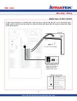
The FMS-1655L provides four relay outputs 

that can be used for remote alarms or pilot 

control functions. The operation of each relay 

can be configured to trigger on defined control 

functions of the FMS-1655L, except for Relay 

2, which is reserved for the display power 

control.

It is often important to have room variables 

such as temperature or relative humidity 

displayed along with the room pressure. 

These variables can be enabled or disabled 

by the user in the 

Display Setup

 menu.

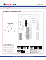
The FMS-1655L provides additional analog 

inputs which can be configured for 4-20 ma 

current or for voltage input signals. The input 

can be scaled as needed to display correct 

values, and a suitable description can be 

applied.

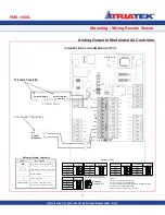
The FMS-1655L provides analog outputs 

which can be set up for 0-5v or 0-10v output. 

It can be programmed to be a proportional 

output for providing a linear signal to an 

automation system, or programmed for a 

PID floating point output for direct control of 

damper actuators, speed drives, etc.

When configured for dual sensor mode (see 

page 35), the FMS-1655L can monitor a 

secondary pressure and display its real time 

measurement on the screen along 

with the primary pressure in a split screen 

vie

w (see Figure 4). This secondary 

monitored pressure re

ading has no alarming 

capabilities and is for display purposes 

only. The Safety Halo™ edge lighting 

continuously displays the alarm status of the 

primary channel, and is not affected by the 

secondary channel.

The user can set multiple access level 

passwords to protect against unauthorized 

access to the FMS-1655L. 

The FMS-1655L provides built-in diagnostic 

tools for troubleshooting during installation, 

including manual override capabilities and 

a comprehensive real-time view that allows 

the real-time values and states of each 

analog and digital input and output to be 

conveniently displayed. This tool facilitates 

the verification and certification processes 

conducted by test and balance personnel 

during commissioning. There are also options 

for storing configuration settings and for 

restoring those settings, as well as performing 

a complete restoration of the factory default 

configuration settings.

-

Summary of Contents for FMS-1655L

Page 1: ...FMS 1655L Installation Manual Version 03 27 17 Triatek FMS 1655L ...

Page 2: ...lation Setpoint Pressure Deadband Analog Output Analog Output Range zero based or offset Analog Output Upper Limit 0 100 Analog Output Lower Limit 0 100 Analog Output Action Direct or Reverse PID Constants Proportional Constant 0 5 100 0 Integral Constant 0 0 100 0 Derivative Constant 0 0 100 0 Alarm Limits Positive Isolation High Alarm Setpoint Positive Isolation High Warning Setpoint Positive Is...

Page 3: ...nt Triatek reserves the right to change product specifications without notice 3 CONTROLLER SETTINGS Audible Alert Operating Mode audible or silent Delay Time Base secs or mins Delay Setting 0 60 Engineering Units Inches of Water or Pascals ...

Page 4: ...he right to change product specifications without notice Warning Failure to follow the wiring diagrams could result in damage to your equipment and could void your warranty Under no circumstances should a single transformer be split between an actuator and controller Doing so will damage the actuator the transformer the controller or all units A single 120 24V 30Va transformer is required for the ...

Page 5: ...tal Input to Door Switch 21 Digital Input to Flow Switch 22 Digital Input to Occupancy Sensor 23 Relay Output to Alarm 24 Relay Output to Warning 25 RelayOutput1 26 Power 27 Isolated Power Supply 28 COMMUNICATIONS WIRING 29 30 FMS 1655L PROGRAMMING Introduction 31 Main Display Screen 31 Configuring Isolation Room Controller 32 Configuring Alarm Limits 32 Set Target Setpoints 32 Setting Up the Anal...

Page 6: ...uivalent Touchscreen User Interface LCD Size 3 2 diagonal LCDType Transmissive Resolution 240 x 320 portrait Viewing Area 50 60 mm x 66 80 mm Color Depth 18 bit or 262K colors Backlight Color White Luminous Intensity min 2500 cd m2 Mechanical FMS 1655L Display Module Housing Surface Mount 3 W x 5 H x 1 13 D FMS 1655L Display Module Housing Flush Mount 5 6 W x 8 5 H x 0 75 D FMS 1655L Controller Ho...

Page 7: ...r the LonWorks network The alarm will automatically reset when the unit senses that room pressure has returned to proper limits or the attendant can mute the audible alarm by touching the Alarm Audible button at the bottom of the screen The FMS 1655L provides four relay outputs that can be used for remote alarms or pilot control functions The operation of each relay can be configured to trigger on...

Page 8: ...without notice FMS 1655L 8 FMS 1655L Surface Mount Case Dimensions Triatek reserves the right to change product specifications without notice 3 5 3 4 3 4 PWR LED GND V Right Side View Left Angle Side View Control Unit Adapter Inside Control Unit 1 13 Cable provided terminated at control unit ...

Page 9: ...NG WIRING Triatek reserves the right to change product specifications without notice The FMS 1655L Flush Mount display is mounted flushed to the wall using the supplied retro fit ring or wall box Use the retro fit ring as a template to mark the wall for cutout ...

Page 10: ...out notice 10 MOUNTING WIRING FMS 1655L Surface Mount Display Triatek reserves the right to change product specifications without notice The FMS 1655L display backplate may be mounted directly to a standard single gang wall box using the two slots along the centerline Use the backplate as a template to mark the mounting holes and the cable access hole at the center of the backplate 3 04 5 05 ø 0 1...

Page 11: ...Controller Mounting Hole Patterns FMS 1655L 11 MOUNTING WIRING Triatek reserves the right to change product specifications without notice ...

Page 12: ...ductor cable from the FMS 1655L controller down wall to the opening of the single gang low voltage mounting bracket Connect cable wires to Vin GND and IO at the sensor s 9 pin connector 6 Attach the flow tube to the sensor port then push the tube and sensor module into place and secure to the mounting enclosure with two 6 32 x 3 4 screws supplied 7 Install the louvered cover plate 8 On the opposit...

Page 13: ... Stainless Steel Flow Tube Mounting Plate Gasket Thin Silicone Caulking apply around tube and between stainless steel plate and wall to seal unit Terminal For connection of transmitter to FMS 1655L Flow Tube When Flow Tube mounting plate is located directly opposite the sensor flow tubing must be cut as short as possible to prevent kinks To FMS Controller Wall Section cutaway view Orange wall brac...

Page 14: ...N ROOM CORRIDOR Stainless Steel Mounting Plate Gasket Louvered Cover Plate Stainless Steel Flow Tube Mounting Plate Gasket Thin Silicone Caulking apply around tube and between stainless steel plate and wall to seal unit penetration Terminal For connection of transmitter to FMS 1655L Flow Tube When Flow Tube mounting plate is located directly opposite the sensor flow tubing must be cut as short as ...

Page 15: ...RLY4 C3 4 C2 C1 RELAY OUTPUTS SHLD DI_3 1 2 3 INT SNSR G 5v V DI FLASH_WP SHLD NETWRK IN NT_2 NT_1 Vsel RNG 4 1 2 3 LED Ain Aout JP4 JP5 RNG mA LED4 JP7 Ain JP3 JP2 FLA FLA 1 1 1 NC No Connection to Field Wiring Field Wiring w space for Number Internal Wiring Screw Terminal Wiring Guide Legend Symbol Description Air Flow To and From Unit Between Room and Corridor Remote Sensor Transmitter GND Io V...

Page 16: ...access the status and the configuration of the unit Also used by configuration software to configure unit Analog Output Unit has 4 analog outputs which can be configured for 0 5 VDC or 0 10VDC Analog Input Unit has 4 analog inputs which can be configured for 4 20 mA 0 5VDC or 0 10VDC Power The FMS 1655L can be powered by either 24 VAC or 24 VDC A 120 VAC to 24 VAC Step Down Isolation Transformer i...

Page 17: ...SNSR DIGITAL IN RLY1 RLY2 RLY3 RLY4 C3 4 C2 C1 RELAY OUTPUTS SHLD DI_3 1 2 3 SELECT INT SNSR G 5v V DI SRVC FLASH_WP 5v GND GND GND SHLD NETWRK IN NT_2 NT_1 AUX PWR OUTPUT Vsel RNG 4 1 2 3 LED Aout JP4 JP5 RNG LED3 LED4 JP7 JP3 1 1 1 Air Control Modulator Optional External Transmitter Power Supply 0 5v JP7 Jumper Setting AI 1 AI 2 AI 3 AI 4 1 2 3 4 JUMPER ON Analog Input 0 10v JP7 AI 1 AI 2 AI 3 A...

Page 18: ..._WP SHLD NETWRK IN NT_2 Vsel RNG LED1 LED Aout LED2 JP4 JP5 RNG JP7 Ain LED1 JP3 LED2 1 1 4 20mA OUT NC No Connection to Field Wiring Field Wiring w space for Number Internal Wiring Screw Terminal Wiring Guide Legend Symbol Description Air Flow To and From Unit Between Room and Corridor Remote Pressure Sensor Io Vin GND 0 5v JP7 Jumper Setting AI 1 AI 2 AI 3 AI 4 1 2 3 4 JUMPER ON Analog Input 0 1...

Page 19: ... GND PH1 PH2 VS SYN IN SASH SNSR DIGITAL IN RLY1 RLY2 RLY3 RLY4 C3 4 C2 C1 RELAY OUTPUTS SHLD DI_3 INT SNSR G 5v V DI SRVC 5v GND GND GND SHLD NETWRK IN NT_2 NT_1 AUX PWR OUT Vsel LED 4 LED3 LED4 JP3 1 Remote Pressure Sensor 1 Remote Pressure Sensor 2 GND Io Vin GND Io Vin 4 20mA OUT 0 5v JP7 Jumper Setting AI 1 AI 2 AI 3 AI 4 1 2 3 4 JUMPER ON Analog Input 0 10v JP7 AI 1 AI 2 AI 3 AI 4 JP7 1 2 3 ...

Page 20: ...D 10v V ANALOG IN 1 2 3 EXT SNSR 5v GND GND GND GND AUX PWR OUTPUT ANALOG OUT RNG 4 1 2 3 Ain 4 Aout JP4 2 JP5 4 RNG 1 mA 3 JP7 Ain JP6 1 1 1 NT_1 NT_2 NETWRK OUT DI_1 DI_2 DI_4 GND GND GND PH1 PH2 VS SYN 24V IN SASH SNSR DIGITAL IN RLY1 RLY2 RLY3 RLY4 C3 4 C2 C1 RELAY OUTPUTS SHLD DI_3 EXT SNSR SELECT INT SNSR G 5v V DI SRVC SRVC FLASH_WP 1 SHLD NETWRK IN NT_2 NT_1 PWR Vsel 1 SW1 LED1 JP2 LED LED...

Page 21: ...I_3 G 5v V DI Vsel 1 1 AO_1 AO_2 AO_3 AO_4 AI_1 AI_2 AI_3 AI_4 GND GND 10v V ANALOG IN NT_1 NT_2 NETWRK OUT GND PH1 PH2 VS SYN 24V IN SASH SNSR RLY1 RLY2 RLY3 RLY4 C3 4 C2 C1 RELAY OUTPUTS SHLD 1 2 3 EXT SNSR SELECT INT SNSR SRVC EXT SRVC SNSR FLASH_WP 5v GND GND GND GND 1 SHLD NETWRK IN NT_2 NT_1 AUX PWR OUTPUT PWR ANALOG OUT 1 SW1 RNG 4 1 2 3 LED1 JP2 LED Ain 4 Aout LED2 1 JP4 2 JP5 4 RNG 1 Tx m...

Page 22: ... JP3 1 1 1 1 1 1 1 1 1 1 1 1 1 1 1 1 1 1 1 1 1 1 1 1 1 1 1 1 1 1 1 1 1 1 1 1 1 1 1 1 1 1 1 1 1 1 1 1 1 1 1 1 1 1 1 1 1 1 1 1 1 1 1 1 1 1 1 1 1 1 1 1 1 1 1 1 1 1 1 1 1 1 1 1 1 1 1 1 1 1 1 1 1 1 1 1 1 1 1 1 1 1 1 1 1 1 1 1 1 1 1 1 1 1 1 1 1 1 1 1 1 1 1JP2 FLA JP2 FLA LED2 1 1 LED3 LED LED LED LED4 LED LED LED 1 1 1 1 1 1 1 1 1 1 1 1 1 1 1 1 1 1 1 1 1 1 1 1 1 1 1 1 1 1 1 1 1 1 1 1 1 1 1 1 1 1 1 1 1 1...

Page 23: ...JP6 1 1 1 1 AO_1 AO_2 AO_3 AO_4 AI_1 AI_2 AI_3 AI_4 GND GND 10v V ANALOG IN NT_1 NT_2 NETWRK OUT GND PH1 PH2 VS SYN IN SASH SNSR RLY1 RLY2 RLY3 RLY4 C3 4 C2 C1 RELAY OUTPUTS SHLD 1 2 3 EXT SNSR SELECT INT SNSR SRVC EXT SNSR 5v GND GND GND GND SHLD NETWRK IN NT_2 NT_1 AUX PWR OUTPUT ANALOG OUT RNG 4 1 2 3 LED Ain Aout 1 JP4 2 JP5 4 1 mA 3 LED3 LED4 JP7 JP6 1 1 1 NC No Connection to Field Wiring Fie...

Page 24: ...1 JP5 RNG LED4 JP7 Ain 1 JP6 JP3 JP2 LED2 1 1 1 1 1 1 AO_1 AO_2 AO_3 AO_4 AI_1 AI_2 GND GND 10v V ANALOG IN NT_1 NT_2 NETWRK OUT DI_1 DI_2 DI_4 GND GND GND PH1 PH2 VS SYN 24V IN SASH SNSR DIGITAL IN SHLD DI_3 1 2 3 EXT SNSR SELECT INT SNSR V DI EXT SNSR FLASH_WP 5v GND GND GND GND 1 SHLD NETWRK IN NT_2 NT_1 AUX PWR OUTPUT ANALOG OUT Vsel RNG 4 1 2 Aout LED2 JP4 JP5 RNG LED4 JP7 Ain JP6 JP3 JP2 FLA...

Page 25: ...ut JP4 2 JP5 4 RNG 1 mA 3 LED4 JP7 Ain JP6 JP2 1 1 1 1 AO_1 AO_2 AO_3 AO_4 AI_1 AI_2 AI_3 AI_4 GND GND 10v V ANALOG IN NT_1 NT_2 NETWRK OUT DI_1 DI_2 DI_4 GND GND GND PH1 PH2 VS SYN IN SASH SNSR DIGITAL IN SHLD DI_3 1 2 3 EXT SNSR SELECT INT SNSR 5v V DI EXT SNSR FLASH_WP 5v GND GND GND GND SHLD NETWRK IN NT_2 NT_1 AUX PWR OUTPUT ANALOG OUT Vsel RNG 4 1 2 3 LED Ain Aout JP4 2 JP5 4 RNG 1 mA 3 LED4...

Page 26: ...D Aout LED2 JP4 1 JP5 RNG LED4 JP7 Ain 1 JP6 JP3 LED2 1 1 1 1 1 1 AO_1 AO_2 AO_3 AO_4 AI_1 AI_2 AI_3 AI_4 GND GND 10v V ANALOG IN NT_1 NT_2 NETWRK OUT DI_1 DI_2 DI_4 GND GND GND PH1 PH2 VS SYN 24V IN SASH SNSR DIGITAL IN SHLD DI_3 1 2 3 EXT SNSR SELECT INT SNSR 5v V DI EXT SNSR FLASH_WP 5v GND GND GND GND 1 SHLD NETWRK IN NT_2 NT_1 AUX PWR OUTPUT ANALOG OUT Vsel RNG 4 1 2 3 LED Aout LED2 JP4 JP5 R...

Page 27: ...3 LED4 JP7 Ain 1 JP6 LED1 JP3 LED2 1 1 1 1 LED4 1 1 AO_1 AO_2 AO_3 AO_4 AI_1 AI_2 AI_3 AI_4 GND GND 10v V ANALOG IN NT_1 NT_2 T_2 NETWRK OUT DI_1 DI_2 DI_4 GND GND GND PH1 PH2 VS SYN SASH SNSR DIGITAL IN RLY1 RLY2 RLY3 RLY4 C3 4 C2 C1 RELAY OUTPUTS SHLD HLD DI_3 1 2 3 EXT SNSR SELECT INT SNSR V DI SRVC EXT SNSR 5v GND GND GND GND 1 SHLD NETWRK IN NT_2 NT_1 AUX PWR OUTPUT ANALOG OUT Vsel 1 RNG 4 1 ...

Page 28: ...60 Hz Black White Stepdown Isolation Transformer provided with FMS Controller Only Class 2 wiring in this compartment Note This product should be installed with the manufacturer provided isolated power supply and connected to an electrical circuit protected by a minimum 20A circuit breaker This circuit breaker should be mounted in an approved electrical enclosure located separately but in close pr...

Page 29: ...CT INT SNSR SRVC EXT SNSR 5v GND GND GND GND AUX PWR OUTPUT ANALOG OUT RNG LED Aout LED2 JP5 RNG LED3 JP7 Ain LED2 1 1 NC No Connection to Field Wiring Field Wiring w space for Number Internal Wiring Screw Terminal Wiring Guide Legend Symbol Description Air Flow To and From Unit Between Room and Corridor LON FTT 10 Free Topology Communications Network 18 22AWG Twisted Pair Cable Type Maximum Node ...

Page 30: ...ated communications problems to a minimum 1 Do not splice communications cable or wire at any point between controllers 2 Avoid the stub T tap technique of routing connecting communications cable Conductor discontinuities produced by such connections may generate RFI or other electromagnetic interference on the communications circuit 3 Do not use wire nut devices for connecting communications cabl...

Page 31: ...eutral isolation mode which is represented by a blue screen with a slashed circle The information that is displayed on the main screen includes the following from top to bottom see Figure 1 Isolation room name in the upper window up to 25 characters Current differential pressure default units in wc Current isolation mode and status Status icon centrally located Current relative humidity in the low...

Page 32: ...then this is the only required step to set up the FMS 1655L Configuring Alarm Limits To determine the limits at which the unit status changes from normal to warning and from warning to alarm the alarm limits must be configured To access the alarm limit settings select the Unit Setup option from the Main Setup Menu At the Unit Setup menu select the Alarm Limits option The high and low alarm limits ...

Page 33: ...dding up to 10 multi level passwords to the system The Password Setup option on the System Setup menu allows the user to manage the security passwords Options on the Password Setup menu include those for adding editing and deleting entries from the system as shown in Figure 7 To add a new password entry select the Add Password option from the Password Setup menu which prompts the user to enter a m...

Page 34: ...ually overridden by selecting the Overrides option from the Diagnostics menu the Analog Outputs option and then selecting the specific analog output to be overridden The user can then in real time dynamically move the damper actuator to a specific position using the slider on the override screen While in override mode the selected analog output is disconnected from its PID control loop if configur...

Page 35: ...ch S1 internal use only 1 Graphics Chip Mode Selection OFF Programming Mode ON Run Mode 2 Touch Screen Calibration Mode OFF Force calibration ON Auto calibration 3 Reserved 4 Reserved Options Dipswitch S2 Product Configuration 1 Sensor Mode OFF Single ON Dual 2 Test Mode OFF Disabled ON Enabled 3 Product Type OFF FMS 1655L ON HMS 1655L 4 Operational Mode OFF Demo Mode ON Run Mode Pushbutton Switch...

Page 36: ...Module Settings 36 Triatek reserves the right to change product specifications without notice MODULE SETTINGS FMS 1655L Triatek reserves the right to change product specifications without notice ...

Page 37: ...acetone tolulene xylene propyl or isopropyl alcohol or kerosene Touching the current name text brings up an alphanumeric keyboard to quickly change the name of the monitored room Touching anywhere else on the screen enters the Main Setup Menu if no password is stored Otherwise a password must be entered before the Main Setup Menu can be accessed Touching the units brings up Engineering Units selec...

Page 38: ... to change product specifications without notice 38 FLOW DIAGRAMS Complete Flow Diagram Due to continuous improvement Triatek reserves the right to change product specifications without notice Triatek reserves the right to change product specifications without notice ...

Page 39: ...FMS 1655L 39 FLOW DIAGRAMS Setup Menu ...

Page 40: ...FMS 1655L Due to continuous improvement Triatek reserves the right to change product specifications without notice 40 Setup Menu FLOW DIAGRAMS ...

Page 41: ...rollers fume hood controllers monitors sensors actuators and more all designed to seamlessly integrate into a facility s building automation system Triatek s customer service is unparalleled Our product support system includes on site installations phone support repairs calibrations and in depth training sessions From our knowledgable engineers and sales team to our talented field technicians Tria...

Reviews: