13
5.5.1.2
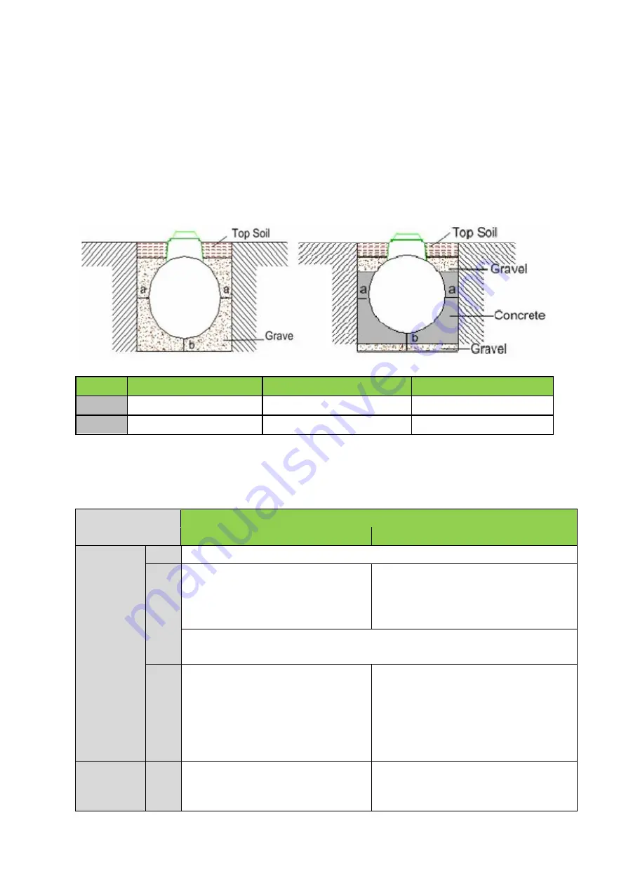
Excavation: Depth
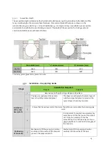
The excavation depth is determined by the inlet and outlet pipes, invert levels relative to the bottom of the
tank, and allowing for the minimum base thickness. Dimension details of the tank are shown on the
relevant drawing, see Section 3.2. Ground instability e.g. running sand may necessitate over-excavation
and stabilization with hard core or blinding concrete. The depth of the excavation for both gravel and
concrete installations are outlined as follows:
Tank Width (mm)
“a” minimum (mm)
“b” minimum
(mm)
Dry Site
1640
250
250
Wet Site
1640
250
300*
*
includes 50mm gravel and 250mm concrete.
5.5.2
Installation
–
Step by Step Guide
Steps
Installation Required
Gravel
Concrete
Installation
of the tank
base/plinth:
1
Remove any soft spots or large stones and boulders.
2
The base is constructed of a 250mm
layer of suitably compacted gravel.
The base is constructed of a 50mm layer of
suitably compacted gravel, covered with a
250mm layer of semi dry concrete.
3
Ensure that base is level and at the correct height to accommodate the incoming pipe
work.
4
It is important to maintain a completely dry
excavation until the final pour of concrete is
set. It may be necessary to line the
excavation with a continuous layer of 1200-
gauge polythene to maintain the integrity of
the concrete.
Positioning
of tank onto
5
Mechanically lift the pumping chamber
carefully into the centre of the hole and
place on the prepared plinth.
Mechanically lift the pumping chamber
carefully into the centre of the hole.
Summary of Contents for Pumping Chamber 2600
Page 7: ...7...
Page 20: ...20...
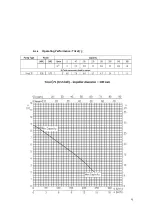
Page 23: ...23 6 1 1 Operating Performance Tricel 75...
Page 24: ...24...
Page 26: ...26 6 2 1 Operating Performance GRI 11...
Page 35: ...35 Notes...


