background image

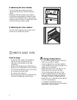
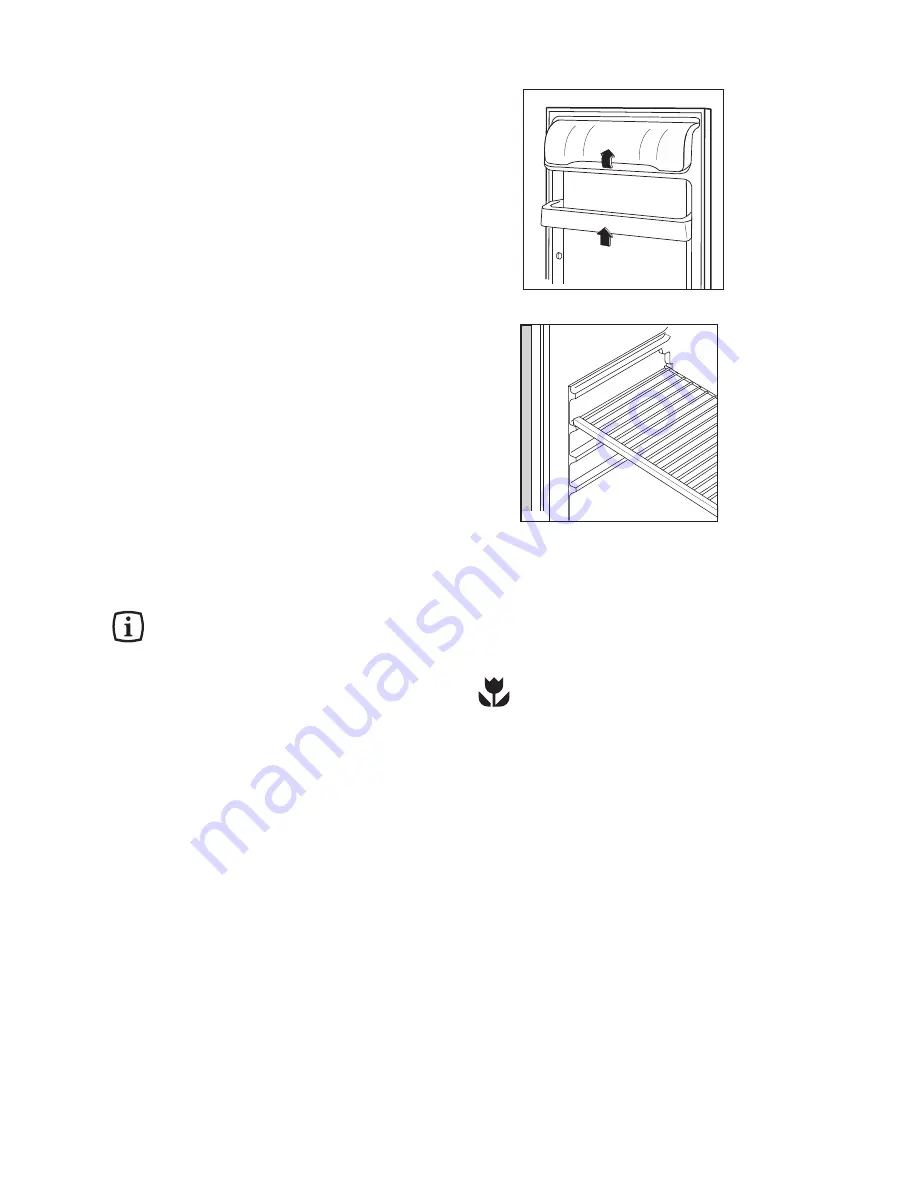
Positioning the inner shelves

The walls of the refrigerator have runners so that

shelves can be positioned as desired.

D040

Positioning the door shelves

The door shelves can be easily removed for

cleaning. Gently ease the shelf in the directions

shown.
Adjustment of the door shelves can be made to

accommodate varying heights of bottles and other

containers. Store light items such as small cartons

and jars on the door shelves. The bottle shelf can be

used for the storage of heavier bottles. 

D758

6

Food Storage

¥ To obtain the best results from the appliance

neither hot foods nor liquids which may

evaporate, should be placed in the larder

compartment.

¥ Keep the time between buying chilled food and

placing it in your refrigerator as short as possible.

¥ Do not push food together too much, try to allow

air to circulate around each item.

¥ Do not store food uncovered.
¥ Remove suspect food from your refrigerator and

clean, refer to Maintenance and Cleaning.

Energy Saving Advice

¥ Do not install the appliance close to sources of

heat, such as a boiler or radiator.

¥ Locate the appliance in a cool well ventilated

room and make sure that the air openings of the

appliance are not obstructed.

¥ Always leave warm food to cool down to room

temperature before placing in the fridge.

¥ Try to avoid keeping the door open for long

periods or opening the door too frequently as

warm air will enter the cabinet and cause the

compressor to switch on unnecessarily often.

¥ Ensure there are no obstructions preventing the

door from closing properly.

¥ It is advisable to peridocally clean the

refrigeration system at the back of the appliance

with a duster or vacuum cleaner.

HINTS AND TIPS

15

Electrical connections

Any electrical work required to install this appliance

should be carried out by a qualified electrician or

competent person.

WARNING: THIS APPLIANCE MUST BE

EARTHED.
The manufacturer declines any liability should

this safety measure not be observed.

If the plug that is fitted to your appliance is not

suitable for your socket outlet, it must be cut off and

the appropriate plug fitted.
Remove the fuse from the cut off plug. 
The cut off plug should then be disposed of to

prevent the hazard of shocks in case it should be

plugged into a 13amp socket in another part of your

home.

Important

The wires in the mains lead are coloured in

accordance with the following code:

Green and Yellow        - Earth
Blue                              - Neutral
Brown                           - Live

If you fit your own plug, the colours of the wires in

the mains lead of your appliance may not

correspond with the markings identifying the

terminals in your plug, proceed as follows:

Connect the Green and Yellow (earth) wire to the

terminal in the plug which is marked with the letter
ÇEÈ or the earth symbol 

or coloured green and

yellow.
Connect the blue (neutral) wire to the terminal in the

plug which is marked with the letter ÇNÈ or coloured

black.
Connect the brown (live) wire to the terminal in the

plug which is marked with the letter ÇLÈ or coloured

red.

D207

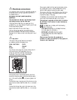
GREEN & YELLOW

13 AMP. FUSE

BROWN

CORD CLAMP

BLUE

13 AMP

The plug moulded onto the lead incorporates a fuse.

For replacement, use a 13amp BSI362 fuse. Only

ASTA or BSI approved fuses should be used.
The plug must not be used if the fuse cover/carrier is

lost. The cover/carrier is indicated by the coloured

insert at the base of the plug.
A replacement cover/carrier must be obtained from

your local Tricity Bendix Service Force Centre.

This appliance complies with the E.E.C. Directive

No. 87/308 of 2.6.87 relative to radio interference

suppression.

This appliance complies with the following

E.E.C. Directives:

73/23 EEC of 19.2.73

(Low Voltage Directive)

and subsequent modifications;

89/336 EEC of 3.5.89 

(Electromagnetic

Compatibility Directive) and subsequent

modifications.

Please ensure that when the appliance is

installed it is easily accessible for the engineer in

the event of a breakdown.

Summary of Contents for TB 80 L

Page 1: ...2222 105 41 TB 80 L FRIDGE OPERATING AND INSTALLATION INSTRUCTIONS ...

Page 2: ...amages to the cooling unit with consequent possible fluid leakages The appliance must not be located close to cookers radiators or boilers Avoid prolonged exposure of the appliance to direct sunlight Do not use other electrical appliances such as ice cream makers inside of refrigerating appliances During Use This appliance is designed for domestic use only specifically for the storage of edible fo...

Page 3: ...ves 6 Positioning the inner shelves 6 Hints and Tips 6 Maintenance and Cleaning 7 Internal cleaning 7 External cleaning 7 When the appliance is not in use 7 Changing the light bulb 7 Defrosting 7 Something Not Working 8 Service and Spare Parts 9 Customer Care 9 Guarantee Conditions 12 Instructions for the Installer Technical Specification 13 Installation 14 Positioning 14 Rear Spacers 14 Electrica...

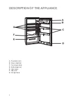
Page 4: ...DESCRIPTION OF THE APPLIANCE 4 A C D G E F B A Thermostat control B Dairy compartment C Can storage shelves D Bottle storage shelf E Salad crisper F Glass shelf G Storage shelves ...

Page 5: ...ling sounds when the refrigerant is pumped through the coils or tubing at the rear to the cooling plate evaporator When the compressor is on the refrigerant is being pumped round and you will hear a whirring sound or pulsating noise from the compressor A thermostat controls the compressor and you will hear a faint ÕclickÕ when the thermostat cuts in and out Fresh food refrigeration To obtain the b...

Page 6: ...r as short as possible Do not push food together too much try to allow air to circulate around each item Do not store food uncovered Remove suspect food from your refrigerator and clean refer to Maintenance and Cleaning Energy Saving Advice Do not install the appliance close to sources of heat such as a boiler or radiator Locate the appliance in a cool well ventilated room and make sure that the a...

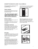
Page 7: ...e condenser black grill and the compressor at the back of the appliance with a brush or vacuum cleaner see figure D273 CONDENSER COMPRESSOR DEFROST TRAY Changing the light bulb Unscrew the light cover and then pull it outward toward the middle of the cabinet Unscrew the bulb and replace it with a new 15 watt bulb available from your nearest Service Force Centre Replace the light cover by sliding i...

Page 8: ...liance if necessary Adjust the thermostat control knobto give correct temperature control See ÒSetting the temperatureÓ Check that the door is closed Large quantities of food have recently been placed in the cabinet and or door is frequently opened Check that air ventilation is not obstructed Refer to normal operating sounds Check the drain hole is not blocked see Maintenance and Cleaning If the a...

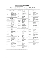
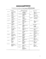
Page 9: ... details under the heading ÔSomething Not Working When you contact the Service Force Centre you will need to give the following details 1 Your name address and post code 2 Your telephone number 3 Clear and concise details of the fault 4 The model and serial number of the appliance found on the rating plate 5 The purchase date For general enquiries concerning your Tricity Bendix appliance or for fu...

Page 10: ...10 ...

Page 11: ...11 ...

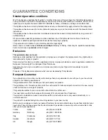
Page 12: ...r calls to put right an appliance which is improperly installed or calls to appliances outside the European Community EC or European Free Trade Area Appliances found to be in use within a commercial environment plus those which are subject to rental agreements Products of Tricity Bendix manufacture which are not marketed by Tricity Bendix European Guarantee If you should move to another country wi...

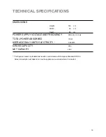
Page 13: ...EQUENCY 220 240 V 50 Hz TOTAL POWER ABSORBED 110 W AVERAGE DAILY UNITS ELECTRICITY 0 55 kWh GROSS CAPACITY 235 l NET CAPACITY 230 l This figure is based on standard test results in accordance with European Standard EN 153 Actual consumption will depend on how the appliance is used and where it is located ...

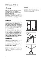
Page 14: ...he plastic bag containing all relevant documentation also contains two spacers to be fitted into special holes in the back of the appliance Fit the spacers into the holes taking care to ensure that the arrow A is positioned as shown in the diagram Then turn them through 45 arrow A vertical until they lock into place DO NOT install in places with restricted ventilation Adjust the level of the appli...

Page 15: ...ich is marked with the letter ÇEÈ or the earth symbol or coloured green and yellow Connect the blue neutral wire to the terminal in the plug which is marked with the letter ÇNÈ or coloured black Connect the brown live wire to the terminal in the plug which is marked with the letter ÇLÈ or coloured red D207 GREEN YELLOW 13 AMP FUSE BROWN CORD CLAMP BLUE 13 AMP The plug moulded onto the lead incorpo...

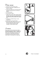
Page 16: ... side 8 Refit the door and bottom hinge 1 on the opposite side 9 Refit the feet 3 on the opposite side 10 Unscrew the handle Refit it on the opposite side after having pierced the plugs with a punch Cover the holes left open with the plugs contained in the documentation pack Attention After completion of the door reversing operation check that the door gasket adheres to the cabinet If the ambient ...

Page 17: ......

Page 18: ......

Page 19: ......

Page 20: ...Tricity Bendix 55 77 High Street Slough Berkshire SL1 1DZ Consumer care telephone number 08705 950950 Electrolux Household Appliances Limited 2000 ...

Reviews: