background image

Z-Wave Remote Control Instructions 

 TrickleStar Ltd 2008 

3

1


 Introduction 

Thank you for purchasing this TrickleStar product. 

With this product you will be able to control a range of Z-Wave™ devices.  

Z-Wave™ is an interoperable two way RF mesh networking technology. 

The TrickleStar Remote Control is a Z-Wave™ enabled device and is compatible with Z-Wave™ enabled devices from a 
range of manufacturers. Each device in a Z-Wave™ network is designed to act as a repeater. Repeaters can re-transmit 
the RF signal to ensure that the signal is received by its intended destination by routing the signal around obstacles and 
radio dead spots. 

The Z-Wave Remote Control is designed to be used with a range of other Z-Wave compliant devices such as dimmers, 
drape controllers and motorised screens. The product is simple yet supports a range of Z-Wave network functionality.  

A Configuration Switch changes between Normal Mode and Configuration Mode. In Configuration Mode the product can 
Include, Exclude and create / remove Assigned Associations, as well as replicate the Routing Table to and from other Z-
Wave  devices.  This  makes  it  ideal  as  a  small,  inexpensive  and  simple  to  use  Portable  Controller  for  installing  and 
configuring  Z-Wave  networks.  The  product  can  act  as  a  Z-Wave  Inclusion  Controller  in  networks  containing  a  Z-Wave 
Static Controller (SIS) such as Gateways, Controls Panels, Set Top Boxes etc.   

The product has 2 buttons available with On/Off or Arrow Up/Down buttons.  The 2 state buttons control a single load or a 
Group and provides confidence of the state that they are switching controlled loads to - as opposed to a simple one button 
toggle type remote control. The buttons can be configured to provide On/Dim Up, Off/Dim Down or All On/Off switching.  

The product is powered by a rechargeable lithium battery.  

The product includes a mini USB connector (which is hidden under a rubber end cap) to allow for recharging via a standard 
PC / Apple Mac USB port. The product can be wall mounted using the wall-mounting cradle. 

Summary of Contents for 200ZW-EU-W

Page 1: ...ctive owners Disclaimer TrickleStar reserves the right to change specifications or designs described in this manual without notice and without obligation Any typographical clerical or other error or omission in this document or other documents or information issued by TrickleStar shall be subject to correction without any liability on the part of TrickleStar without notice Save Money Save Power Sa...

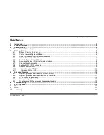
Page 2: ... 8 4 6 Associating Devices to Remote Operation Buttons 8 4 7 Clearing Group Association 9 4 8 Enabling All On Off Functionality 9 4 9 Resetting the Controller 9 4 10 Operation On Off Dim 10 4 11 Operation All On Off 10 5 Advanced Features 10 5 1 Replicating Network Information to another Controller 10 5 2 Replicating Network Information from another Controller 11 5 3 Create Assigned Association 12...

Page 3: ... Mode and Configuration Mode In Configuration Mode the product can Include Exclude and create remove Assigned Associations as well as replicate the Routing Table to and from other Z Wave devices This makes it ideal as a small inexpensive and simple to use Portable Controller for installing and configuring Z Wave networks The product can act as a Z Wave Inclusion Controller in networks containing a...

Page 4: ...Z Wave Remote Control Instructions TrickleStar Ltd 2008 4 2 Product Overview ...

Page 5: ...ovals Z Wave Protocol Release 5 01 Operating Temp 0 to 45 C EU US RF Data Rate 9 6kbps 40kbps RF Frequency 9 6kbps 868 42 MHz 40kbps 868 40 MHz 9 6kbps 908 42 MHz 40kbps 908 40 MHz RF Range Typical 30 meters RF Other EU CE US FCC CSA 2002 95 EG RoHs 2002 96 EC WEEE 1999 5 EC RTTE Z Wave TM Certified ...

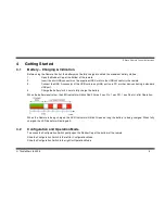
Page 6: ...ther devices having a standard USB port 4 Charge the battery for 4 hours to fully charge the battery When the battery level is low the LED Indicator will blink Red 3 times 1 sec On 1 sec Off 1 sec On etc after Operation When the Remote is being charged the LED Indicator will blink Green as long the battery is being charged When fully charged the LED Indicator will extinguish 4 2 Configuration and ...

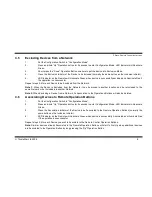
Page 7: ...LL devices to be inserted into a Network have been Reset Devices which have already been Included into a network cannot be Included into a new Network before the have been Excluded Reset 4 4 Including Devices to a Network 1 Put the Configuration Switch in Configuration Mode 2 Press and hold Up Operation button for 2 seconds to enter Configuration Mode LED Indicator will illuminate Green 3 Short pr...

Page 8: ...uded to the same Network or be Included into another Network Note 2 When Excluding a Device from a Network its Association to the Operations Buttons will also be deleted 4 6 Associating Devices to Remote Operation Buttons 1 Put the Configuration Switch in Configuration Mode 2 Press and hold Up Operation button for 2 seconds to enter Configuration Mode LED Indicator will illuminate Green 3 Press th...

Page 9: ...e control can act as an All On All Off Controller which allows all the devices in the Network to be turned On or Off at the same time 1 Put the Configuration Switch in Configuration Mode 2 Press and hold Up Operation button for 2 seconds to enter Configuration Mode LED Indicator will illuminate Green 3 Short press the Up Operation Button five times within 2 5sec to configure the device to become a...

Page 10: ... blink Green DIM DOWN Press and hold the ʻDownʼ button LED Indicator will blink Yellow When an operation is completed successfully all Associated devices were controlled the Remote Control LED Indicator will illuminate Green for 3 sec and Red for 3 sec if the operation was unsuccessful Note Relay devices binary switches will stay in their current state when dimming up or down 4 11 Operation All On...

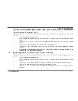
Page 11: ...tion Receive initiator on the Secondary Controller 5 Replication will start and Remote Control LED Indicator will blink Green when transferring Network Information 6 LED Indicator on the Remote will illuminate Green for 3 sec when Replication is completed successfully and illuminate Red if the operation is unsuccessful 5 2 Replicating Network Information from another Controller To Replicate the Ne...

Page 12: ...iation Initiator on the Device controlling the other device LED Indicator on the Remote will illuminate Green when Assigned Association is successfully and illuminate Red if the operation is unsuccessful 5 4 Remove Assigned Association 1 Put the Switch in Configuration Mode 2 Press and hold Up Operation button for 2 seconds to enter Configuration Mode LED Indicator will illuminate Green 3 Short pr...

Page 13: ...e be Associated to the Operation Buttons Try to create an Association 7 FCC Statement This device complies with part 15 of the FCC rules Operation of this device is subject to the following conditions This device may not cause harmful interference and This device must accept any interference including interference that may cause undesired operation Note This equipment has been tested and found to ...

Page 14: ...he warranty During the one year period beginning on the invoice date TrickleStar will repair or replace Products returned to TrickleStarʼs facility Customer must prepay shipping and transportation charges and insure the shipment or accept the risk of loss or damage during such shipment and transportation TrickleStar will ship the repaired or replacement products to Customer freight prepaid Trickle...

Page 15: ...or use or for data or software which is lost corrupted deleted or altered TrickleStar shall not be liable to the Customer for any incidental indirect special or consequential damages arising out of or in connection with the purchase use or performance of products or services even if TrickleStar has been advised of their possibility 9 WEEE This product complies with the WEEE Directive 2002 96 EC ma...

Page 16: ...e Network Only Primary Controller can Include Devices to a Network Secondary Controller Additional Controller used in a Network It contains network information about other devices within the Network Primary Controllers cannot Include new Devices to a Network Inclusion Controller Controller within a SUC SIS Network used to configure a Network It contains network information about other devices with...

Page 17: ...nstallation If this equipment does cause harmful interference to radio or television reception which can be determined by turning the equipment off and on the user is encouraged to try correct the interference by one or more of the following measures 1 Reorient the receiving antenna 2 Increase the separation between the equipment and receiver 3 Connect the equipment into and outlet on a circuit di...

Reviews: