Trident Emergency Products, LLC
2940 Turnpike Drive | Suite #9 | Hatboro, PA 19040 USA
10
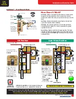
AirPrime
™ Fire Pump Priming System
™
5.22"
2.00"
1.00
"
2.50"
2.38"
1.125"
.281" Hole
Panel Cutout
3.22"
.781"
Manual Single Location AirPrime
™
Systems
Installation
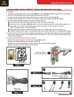
1. Install the primer within pump enclosure. Unit must be
VERTICAL
and mounted
ABOVE
the highest priming point in the suction piping.
2. Install the manually operated
Push To Prime
control on the pump panel (see
Figure #13
).
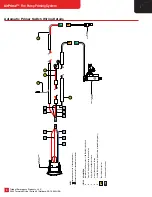
3. Install 3/8"
OD
air hose tubing with 1/4" NPT fittings from the pressure protected air tank (PPV valve) to the primer control and then to
the primer unit. (See
Figure #14
).
4. If the AirPrime is equipped with the optional lift gauge, connect 1/4" air hose tubing from the push to connect fitting supplied on the
back of the panel lift gauge to the 1/8" NPT connection on side of the primer body using the 1/8" male NPT x 1/4"
push to connect
swivel elbow provided with the AirPrime unit. (See
photo bottom right
for tubing connection location).
2.00"
Panel Cutout
.281" Diameter
.781"
1.00"
3.22"
3.22
1.125
"
OPERATION: Manual Priming Control
The manual fire pump primer is operated simply by increasing the engine speed to a maximum of 1000 RPM and depressing the push
button on the panel. Hold the button down until the discharge pressure gauge begins to rise. The primer will stop operating when the push
button is released. The push button will operate the primer regardless of whether the fire pump is engaged or not.
• Depressing the
Push To Prime
button directs air to the primer inlet.
• An internal valve to the fire pump is opened with air pressure from the chassis air brake system when the button is depressed.
• Vacuum for drafting is created by air flowing through multi-stage internal venturi nozzles.
• The Primer Control Valve has no water, plumbing or electrical lines.
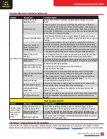
• Never run a dry pump at engine speeds above 1200 RPM for more than 45 seconds in accordance with the operating instructions
provided from the fire pump manufacturer.
• NOTE
: It is recommended that the
Push Button Control
be depressed monthly to exercise the spring and seals
. The fire pump
does not have to be engaged during this process. This also applies to any other intake Push Button Controls you may have.
or equivalent O-Ring safe lubricant should be applied annually to lubricate the mechanism. It is available at
or
through a local automotive parts supplier.
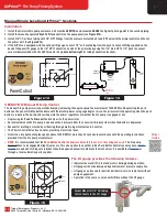
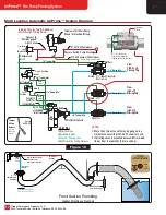
Figure 13
Figure 14
Primary Air Supply
Panel
Push
Button
™
Pressure
Protection
Valve
Plugged
Opening
Filter
Port
Figure 15
The lift gauge provides the following features:
• Indicates the water lift in feet and meters during priming operation.
• Lift gauge will not be damaged by positive water pressure supply line.
• Lift gauge can be used for positive periodic in-service ramp test without
pump engagement.
• Operation is the same as a manual AirPrime without the lift gauge.
Swivel Elbow for 1/4" OD tubing
that connects to the Lift Gauge.
Parker
O-Lube


