(
215-293-0700
7
215-293-0701
11
Installation and Operation Guide
Proven
Priming
Performance
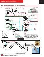
Multi Location Installation and Operating Instructions
Key Points for All Installations
1. The AirPrime unit
MUST
be
VERTICALLY
mounted
ABOVE
the highest priming point in suction piping.
2. All Remote Priming Valves (RPV)
MUST
be mounted
ABOVE
the highest priming point in the suction piping.
3. If the RPV priming valve is mounted below the AirPrime unit, add drain lines from all low points to a drain valve to prevent freezing.
4. It is common to have up to four (4) remote locations with AirPrime Multi-Location priming systems.
5. If front suction pre-priming is required, refer to drawings on the bottom
Pages 11
and
12
for installation recommendations.
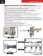
Installation Notes for Multi-Location Priming Systems
1. For
Automatic System
: Follow the instructions on
Page 6
and
Page 7
with lift gauge for mounting the first control on the pump panel.
2. For
Automatic System
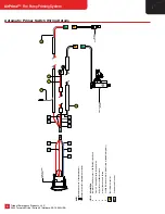
: Refer to schematic in
Figure 17
on
Page 11
for air tubing, electric wiring and suction plumbing.
3. For
Automatic AirPrime Connections
: See
Figure 7
on
Page 6
and information on
Page 5
.
4. For
Manual System
: Follow the instructions on
Page 8
for mounting the first control on the pump panel.
5. For
Manual System
: Refer to schematics in
Figure 16
on
Page 10
for air tubing and suction piping.
6. For additional priming locations mount a Push-Button Control as shown in
Photo 5
.
7. Identifying
Gold Labels
are provided for
LEFT
,
RIGHT
,
FRONT
and
REAR
remote priming locations as shown in
Photo 6
.
8. See
Photos 3
and
4
to note that the cast in arrows on the RPVs and Check Valves are in the proper flow direction.
Operating Instructions for Multi-Location Automatic Priming System
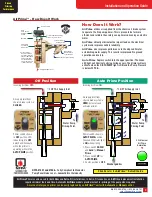
1. See operating instructions for the Auto Priming System on
Page 6
for the initial fire pump priming procedures.
2. Be sure the AirPrime switch is in the
AUTO
PRIME
position when opening a remote location valve control.
3. To pre-prime a remote location, push in the
PRIME
button of that location for 45 seconds or until water appears at top of the hose.
Operating Instructions for Multi-Location Manual Priming System
1. Refer to the operating instructions for Manual Priming System on
Page 8
for the initial fire pump priming procedures.
2. To pre-prime a remote location, push in the
PRIME
button for that location for 45 seconds or until water appears at top of the hose.
3. Be prepared to push the
FIRE PUMP
PUSH TO PRIME
button when a remote location valve is opened to remove any trapped air.
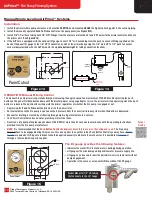
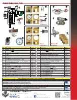
Multi-Location Components
1. Primer solenoid and Multi Location air inlets are shown below in
Photos 1
and
2
.
2. The Remote Priming Valve (RPV) and Air Line Check Valve include flow direction arrows as shown in
Photos 3
and
4
below.
3. Additional pre-priming panel control valve and location labels are shown in
Photos 5
and
6
.
Front View of
AirPrime
Unit
Solenoid
Air Supply
Connection
Additional
Air Inlets
Plug the
Unused Ports
™
1
2
3
4
5
6
Flo
w D
ire
ctio
n
Air
Flo
w
12/24 Volt Solenoid Valve
Manual AirPrime/Remote Location Valve
Air Line Check Valve
Remote Priming Valve (RPV)
Remote Priming Valve Labels
Auto AirPrime Air Connection Ports


