Trident Emergency Products, LLC
2940 Turnpike Drive | Suite #9 | Hatboro, PA 19040 USA
4
AirPrime
™ Fire Pump Priming System
™
Installer Responsibilities
Air Compressor Size
1. The 2-barrel AirPrime must be used only on fire pumps rated 1000 GPM
[3800 LPM]
and less. A minimum air compressor size of 13.2
CFM
[0�374 Cubic Meters per Minute] must be used
.
2. The 3-barrel AirPrime must be used only on fire pumps rated 1250 GPM
[4700 LPM]
and more. A minimum air compressor size of 15.6
CFM
[0�442 Cubic Meters per Minute] must be used
.
3. For Industrial Pumpers The
Dual Unit
requires an air compressor with capacity greater than 20 CFM
[6�09 Cubic Meters per Minute]
. The
Triple Unit
requires an air compressor with capacity greater than 30 CFM
[9�14 Cubic Meters per Minute]
.
4. NOTE
: For operations above 4000 feet
[1219 meters]
of elevation and lifts greater than 15 feet
[4�5 meters]
, a minimum air compressor
size of 18 CFM
[0�510 Cubic Meters per Minute]
or
larger is required.
Basic Materials Supplied by Installer
1. A 3/8" OD (.251 ID) air hose from the air tank (primary or auxiliary tank) with 1/4"
NPT
connections
(length determined by installer).
2. Primer mounting bracket to
install high in the pump enclosure
. (Only required for remote mount.)
See
Figure #2
.
3. Non-collapsible 3/4" inside diameter (ID) air hose from primer to fire pump with 3/4" NPT fittings.
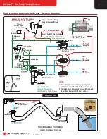
4. A Pressure Protection Valve (PPV) (Optionally available from Trident,
Part # 30.053.0
).
5. A 1-1/4"
[32 mm]
ID drain hose may be connected to the primer outlet using a hose clamp to secure
it in place.
NOTE:
Loosely tighten the hose clamp to avoid damage to the discharge ports. This
hose directs water from the primer to any location under the vehicle. Be sure this hose is properly
secured, short as possible and away from any moving components, free of any sharp bends and
pitched to allow drainage.
6. Liquid thread sealant or Teflon tape is required for all threaded pneumatic fittings.
NOTE:
Use sparingly while applying sealant to avoid blockage of the internal mesh filter. See
Page 5
,
Figure #5.
Remote Primer Mounting
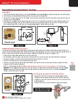
1. A fabricated primer bracket to secure the primer within the pump enclosure. The mounting height for all priming components must be
ABOVE
the highest priming point on the pump suction side (or above the highest remote priming valve for multiple location systems) to
permit air removal and allow for complete drainage. See
Figure #2
for the bolt hole mounting template. An actual size bolt hole template
is provided in the primer shipping carton for your convenience.
NOTE:
Primer
MUST
be mounted
VERTICALLY
with the primer outlet discharge (round) ports facing downward as shown in
Figure #1
.
2. A non-collapsible hose from the 3/4" NPT cleanable wye strainer on the primer inlet to the 3/4" NPT fire pump priming port.
A 3/4" minimum inside diameter hose must be used.
3. The AirPrime and attached wye strainer must be installed in a location for ease of maintenance per
Figure #3
on
Page 5
. The installer
may choose from one of the options below as a method of draining the strainer:
a) Remove threaded plug on wye strainer for draining during annual pump service. Refer to
Page 13
for Troubleshooting Guide.
b) For draining, the strainer may be piped to the pump master drain by the installer. This helps in climates prone to freezing conditions.
c) Alternatively a separate drain with valve and label may be piped to the bottom of the pump enclosure by the installer.
NOTE
: If the vehicle includes a front suction inlet, adding a
Primer Front Intake
control is required. Refer to drawings of front suction
plumbing on
Pages 11
and
12
.
1.563"
2.00"
2.00"
.625"
(4) Mounting Holes
1/4"-20TPI x 5/8" Deep
Primer
Outlet
Primer Body
Mounting Template
Pump
Body
O-Ring
Hale
Black
Plastic
Strainer
Primer
Outlet
Hale Direct Mount
For
Q Series
Pump
™
™
Figure 2
Figure 1
Primer Mounting
Figure #1
Shows the proper mounting of
the primer to a Hale
Q Series
cross-frame
midship fire pump. Use the black plastic
strainer that Hale supplies with the fire pump.
Figure #2
Shows the dimensions for the
tapped holes in the primer body.


