(
215-293-0700
7
215-293-0701
13
Installation and Operation Guide
Proven
Priming
Performance
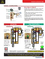
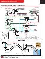
Multi Location Manual AirPrime
™
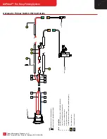
System Diagram
Figure 17
™
3/4" Tubing (Min)
Plumb To
Drain Valve
Strainer
3/8" Tubing (Min)
3/8" Tubing
(Min)
1/4" Tubing (Min)
3/8" Tubing (Min)
Check Valve
From
FIRE Pump
RPV
Fire Pump
Open
3/4" Tubing (Min)
Closed
Position
Compressed Air In
From
Remote Location
Panel Valve
Fire Pump
RPV
Remote Location
Open
Position
Closed
1/4" Tubing (Min)
3/8" Tubing (Min)
3/4" T
ubing (Min)
3/4" Tubing (Min)
Check Valve
Color Key
Air Supply Lines
Vacuum Priming
Lines
Panel Valve
Remote
Drawing Denotes One (1)
Additional Priming Location
™
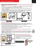
Color Key
3/4" ID External Flex Line to Low Point Drain
1/2" ID Internal Flex Line
3/4" ID External Flex Lines
1/2" or 5/8" ID External Flex Line
1/2" ID Internal
Flexible Tubing
**
Priming Line
Drain Valve
**
1/2" or 5/8" ID
External Flexible Tubing
**
3/4" Weld Coupling
**
3/4" ID External Flex Tubing
**
Merge All "High Point" Pickups
At The Valve Location (Higher Than The "High Points")
Fittings In Kit From
Outside Of Pipe
To Inside
*
Priming
Valve
Closed
5" or 6"
Butterfly Valve
By Builder
**
Front Axle Area
3/4" ID External Flex Tubing
**
Special Strainer
*
*
Trident Kit Supplied Items
**
Installer Supplied Items
Kit Part Numbers
5
" NH Kit: #27.011.1
6
" NH Kit: #27.011.0
Contact Trident for Front Suction Kits.
Front Suction Plumbing
Highest Point at Front Inlet
Use one of these ports
for Green Air Supply line.
Plug the unused 1/8" NPT Port.
Leave Open
for vent.


