background image

MAINTENANCE

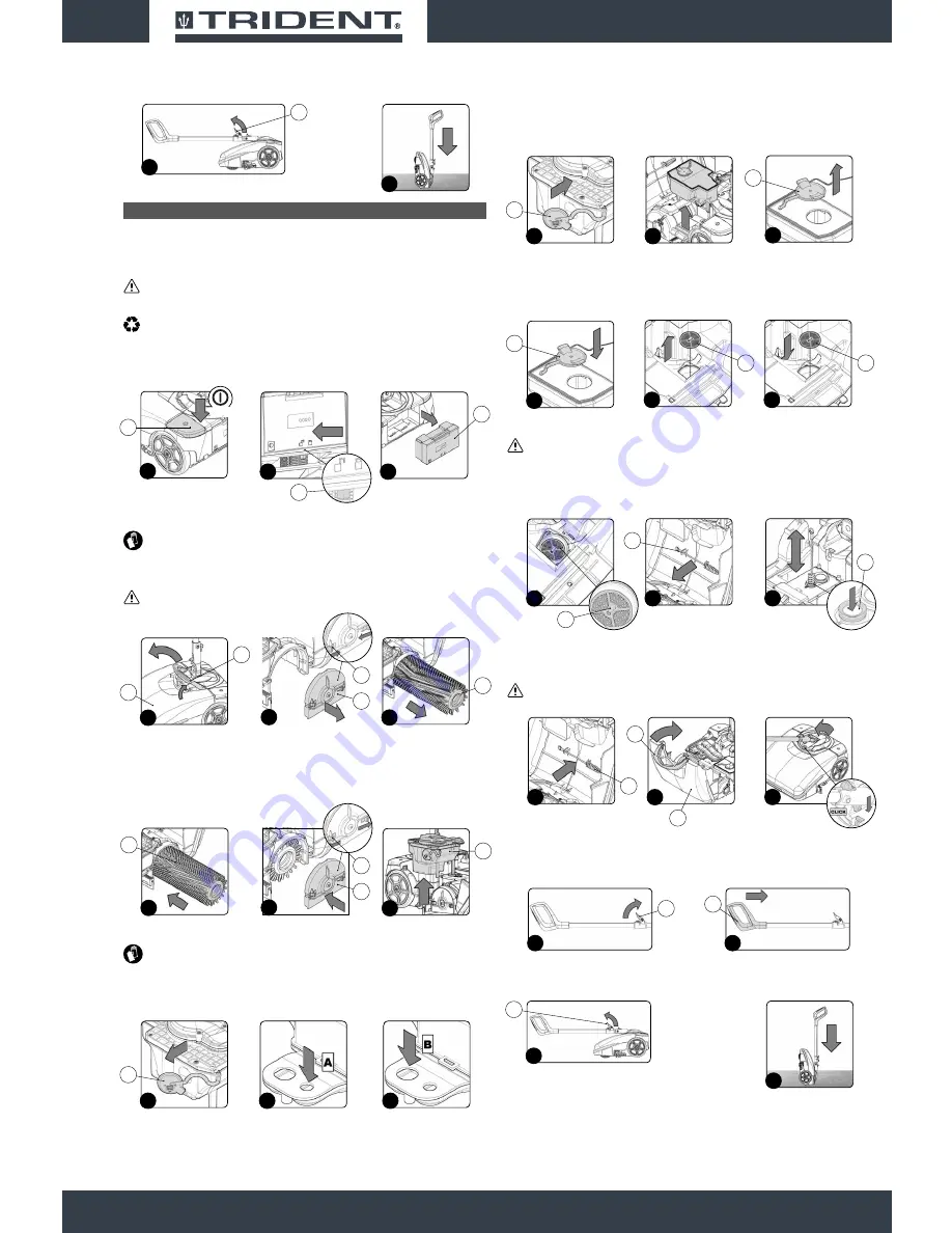
At the end of the work, and before carrying out any type of maintenance, perform the following 

operations:

1. 

Switch off the machine using the main switch (1) (

Fig.1

).

2.  Rotate the handlebar so it is vertical.

CAUTION

: During this operation, do not rest your foot on the machine.

3.  Take the machine to the designated maintenance area.

N.B

: the place designated for this operation must comply with current environmental protection 

regulations.

4.  Remove the battery (2) from the battery compartment; to free the battery, shift the stop lever (3) in 

the direction of the arrow (

Fig.2

).

5.  Remove the battery from the battery compartment using the handle moulded on it (

Fig.3

).

6.  Rotate the front carter (4) as far as it will go - do this with the aid of the handle (5) (

Fig.4

).

CAUTION

: these operations must be carried out using protective gloves to avoid any possible 

contact with the edges or tips of metal objects.

7.  Remove the tunnel cover (6) and shift the stop levers (7) as indicated by the arrows (

Fig.5

).

8.  Remove the brush (8) from the machine (

Fig.6

).

ATTENTION:

 During this operation, keep the control handlebar still, in order to prevent the 

machine from moving accidentally.

9.  Clean the brush under running water and remove any impurities present in the bristles of the brush. 

Check that the bristles are not worn; in the event of excessive wear, replace the brush (the bristles 

should be at least 10 mm long).

10. Fit the brush (8) on the pin in the brush motor (the brush can only be inserted in one direction) 

(

Fig.7

).

11. Replace the tunnel cover (6) and shift the stop levers (7) as indicated by the arrows (

Fig.8

)

12. Remove the recovery tank (9) from the machine (

Fig.9

).

13. Remove the drain plug (10) on the recovery tank from its seat (

Fig.10

).

ATTENTION

: protective gloves should always be worn before handling detergents or acidic or 

alkaline solutions, to avoid serious injury to the hands.

14. Clean with a jet of air

 the vacuum motor air channel chamber, the chamber inlet hole is marked 

with the letter (A) (

Fig.11

).

15. Clean with a jet of air

 the dirty water channel chamber, the chamber inlet hole is marked with the 

letter (B) (

Fig.12

).

16. Rinse the inside of the tank with a jet of water.

17. Insert the drain cap (10) in its seat on the detergent solution tank (

Fig.13

).

18. Remove the solution tank from the machine (

Fig.14

).

19. 

Remove the filling cap (11) from its seat on the solution tank (

Fig.15

).

20. Rinse the inside of the tank with a jet of water.

21. 

Replace the filling cap (11) in its seat on the detergent solution tank (

Fig.16

).

22. 

Remove the filter cartridge (12) and clean it under a jet of water to remove any impurities that might 

be attached. If necessary, replace it (

Fig.17

).

23. 

Insert the filter cartridge into its seat in the frame (12) (

Fig.18

).

ATTENTION:

 Put the filter cartridge in its seat as shown in 

figure 19

, the valve activation pin 

(13) should be facing up.

24. 

Insert the two tanks in the machine, positioning first the solution tank and then the recovery tank.

25. Remove the vacuum duct cleaning brush (14) from its support (

Fig.20

).

26. Clean the inside of the vacuum duct (15) with the brush (14) (

Fig.21

).

27. Put the vacuum duct cleaning brush (14) in its support (

Fig.22

).

28. Rotate the front carter (4) as far as the work position; do this with the aid of the handle (5) (

Fig.23

).

29. Block the handlebar in the horizontal position (

Fig.24

).

ATTENTION:

 During this operation, do not rest your foot on the machine.

30. Turn the stop lever of the command handlebar (16) in the direction of the arrow (

Fig.22

).

31. Close the command handlebar again, pushing the handle (17) towards the body of the machine 

(

Fig.23

).

32. Turn the stop lever of the command handlebar (16) in the direction of the arrow (

Fig.24

).

33. 

Position the machine with its rear in contact with the floor (

Fig.25

).

12

10

10

11

12

17

16

10

10

13

14

11

15

1

1

OFF

3

2

2

3

5

4

4

8

6

6

5

7

9

9

8

6

7

8

7

11

16

17

18

12

12

19

13

20

21

14

15

5

4

23

14

22

24

22

16

23

17

24

16

25

Summary of Contents for NM14

Page 1: ...Scrubbing machine ORIGINAL INSTRUCTIONS DOC 10075414 Ver AA 11 2017 Use and Maintenance manual ...

Page 2: ......

Page 3: ...CAUTION Indicates a probable dangerous situation that could cause minor injuries ATTENTION Indicates a probable dangerous situation that could damage objects N B Indicates a note regarding essential or useful functions CONSULTATION Indicates the need to consult the Operator s Manual before performing any operation GENERAL SAFETY REGULATIONS CONTENTS 3 GENERAL SAFETY REGULATIONS 3 RECHARGING THE BA...

Page 4: ...arefully read the user manual of the battery charger you want to use before recharging Do not disconnect the battery charger from the mains socket with wet hands RECHARGING THE BATTERIES DANGER In the event of danger quickly press the machine s main switch and remove the battery from the battery compartment Never collect gases explosive inflammable liquids or powders nor acids and solvents These i...

Page 5: ... machine must only be used and stored in an enclosed or covered environment The machine must not be used or stored outdoors in damp conditions or directly exposed to rain The machine does not cause harmful vibrations Use the machine only in the manner described in this manual Do not collect inflammable or steaming refuse like cigarettes matches and hot embers Always follow the instructions on the ...

Page 6: ...ust be protected from any accidental movements CAUTION In order to prevent the unauthorised use of the machine the power supply must be interrupted switch the machine off using the main switch remove the battery from the battery compartment ATTENTION The machine must only be stored under temperature conditions ranging from 32 F to 104 F The humidity level must be between 30 and 95 DEACTIVATION OF ...

Page 7: ...ean the machine with direct or pressurized jets of water or with corrosive substances Have the machine checked by an authorised technical assistance centre every year When disposing of consumable materials observe the laws and regulations in force Once the machine has reached the end of its service life the materials contained within it must be disposed of in an appropriate manner keeping in mind ...

Page 8: ...could compromise its legibility ON CONSIGNMENT OF THE MACHINE When the machine is consigned to the customer an immediate check must be performed to ensure all the material mentioned in the shipping documents has been received and also to check the machine has not suffered damage during transportation If this is the case the carrier must ascertain the extent of the damage at once informing our cust...

Page 9: ... place in compliance with the directives in force so that it cannot slide or tip over CAUTION these operations must be carried out using protective gloves to avoid any possible contact with the edges or tips of metal objects BATTERY TYPE To power the appliance use only the battery supplied in the packaging or one supplied by a specialised technician OTHER BATTERY TYPES CANNOT BE USED The machine i...

Page 10: ... vertical CAUTION During this operation do not rest your foot on the machine 3 Start the machine using the main switch 1 Fig 1 N B If the LED of the main switch 1 Fig 1 is lit up this means there is electrical continuity 4 Check the battery charge level There are four LEDs 2 on the battery to show the charge percentage Fig 2 If all the LEDs are lit up the battery is fully charged if they are all s...

Page 11: ...and rotate the knob 2 in the direction of the arrow Fig 2 N B Fig 2 shows the left side of the machine Rotate the knob on the right hand side in the opposite direction 4 Take the machine to the designated place for draining off the dirty water ATTENTION the place designated for this operation must comply with current environmental protection regulations 5 Remove the battery 3 from the battery comp...

Page 12: ...erious injury to the hands 14 Clean with a jet of air the vacuum motor air channel chamber the chamber inlet hole is marked with the letter A Fig 11 15 Clean with a jet of air the dirty water channel chamber the chamber inlet hole is marked with the letter B Fig 12 16 Rinse the inside of the tank with a jet of water 17 Insert the drain cap 10 in its seat on the detergent solution tank Fig 13 18 Re...

Page 13: ...ition Fig 43 46 Block the handlebar in the vertical position to release the handlebar move the latch 30 in the direction of the arrow Fig 44 47 Rotate the front carter 4 as far as it will go do this with the aid of the handle 5 Fig 45 48 Insert the two tanks and the detergent solution filter cartridge in the machine positioning first the detergent solution filter cartridge then the solution tank a...

Page 14: ...TION ON THE BRUSH The brush is not correctly inserted in the machine Insert the brush correctly in the machine The brush bristles are subject to excessive wear Check the condition of the brush and replace it if necessary read MAINTENANCE THE SQUEEGEE DOES NOT DRY PERFECTLY The vacuum device is obstructed Remove the obstructions from the squeegee body read MAINTENANCE Remove the obstructions from t...

Page 15: ......

Page 16: ...HILLYARD INDUSTRIES PO Box 909 St Joseph Missouri 64502 0909 U S A Telephone 816 233 1321 www hillyard com ...

Reviews: