USING THE COOKTOP
Gas burners
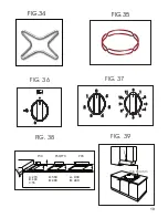
The delivery of gas to the burners is controlled by the knobs shown in fig. 3
6
that in turn control the
taps. The symbols, depending on the various versions, may be printed on the knobs or on the
control panel. By moving the indicator to coincide with the printed symbols, the following
adjustments can be made:
O
Tap closed, no gas delivery
Maximum capacity, maximum gas delivery
Minimum capacity, minimum gas delivery
Burner ignition
- Burners without safety valve
To light burners without electric ignition, or to light those with ignition during a power cut, place a
naked flame next to the top of the burner, press the corresponding knob down and turn anti-
clockwise until the symbol
coincides with the reference mark on the control panel.
For minimum gas delivery, turn the knob until the indicator points to the small flame.
The setting must always be positioned between the maximum and minimum, and never
between the maximum setting and the off position.
To switch the burner off, turn the knob clockwise to the position
“tap closed”
- Burners with electric ignition
Models with ignition switch
To light one of the burners, press the ignition switch and turn the corresponding knob to the
maximum delivery position (symbol
). Hold the switch down until the burner lights, then adjust the
flame by turning the knob to obtain the desired intensity.
Models with ignition incorporated in the control knobs
These models are identified by the symbol
next to the symbol
( Maximum delivery).
To light one of the burners, press the knob down and turn it to the maximum delivery position,
holding down until the burner lights. Next adjust the flame by turning the knob to obtain the desired
intensity.
6. Semirapid right burner (SR)
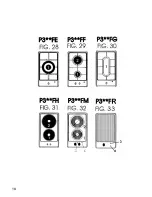
Mod: P3(**)FH
(Fig. 31)
1.
Electric hotplate ø 145
2.
Electric hotplate ø 180
Domino Cooktops
Mod: P3(**)FE
(Fig. 28)
1.
Triple crown burner (TC)
Mod: P3(**)FM
(Fig. 32)
1. Hotplate
ø
145
2. Hotplate
ø
180
3.
Appliance ON indicator
4. Residual heat indicator
Mod: P3(**)FF
(Fig. 29)
1.
Auxiliary burner (A)
2.
Rapid burner (R)
Mod: P3(**)FR
(Fig. 33)
1.
Grill plate measuring
ø
350
x 2
00
3
.
Power
signal
4
. Residual heat signal
Mod: P3(**)FG
(Fig. 30)
1.
Fish kettle burner (P)
4
Summary of Contents for built-in cooktops
Page 1: ...INSTRUCTIONS BOOKLET built in cooktops ...
Page 2: ......
Page 16: ...14 ...
Page 17: ...15 ...
Page 18: ...16 ...
Page 19: ...17 ...
Page 20: ...18 ...
Page 22: ...C Min 3 mm D E Min 10 mm 20 FIG 41 FIG 40 FIG 42 FIG 43 FIG 44 FIG 45 ...
Page 25: ...23 ...
Page 26: ...24 ...
Page 27: ......
Page 28: ...01Q038 ...


