16
ASSeMBLiNg THe BOiLer
!
CAUTION
These baffles will generate higher efficiencies and lower
stack temperatures. Under certain conditions, a lower gross
stack temperature entering the chimney has the potential
to be cooled below the dew point and create condensate on
interior surfaces. Flue gas condensate is corrosive, which
requires special consideration and must be addressed im-
mediately. DO NOT install baffles until you have read the
section regarding Venting completely.
Connect the Field Wiring.
18.
See Section
Electrical Connec-
tions
as well as
Figure #10
&
#11.
Route the wire harnesses from the LWCO (optional), the
A.
High Level Manual Reset (optional) and the harness from
the Aquastat through the rear jacket panel. (See
Figure #11
)
Connect the molex plugs on the end of each wire harness to its
respective plug on the control panel.
If the optional Low Water Cut Off and/or optional High
B.
Temperature Limit Manual Reset are not used, ensure supplied
jumpers are installed. See
Figure #11
.
Connect the wiring harness from the Aquastat to the circula-
C.
tor. See
Figure #10
.
120 volt power supply field wiring will enter through jacket
D.
rear panel.
Wire the power supply as shown in
E.
Figure #11
.
Connect the
green wire to the grounding lug. When installing the wiring
through the hole in the control panel, be sure to use an anti
abrasion cable clamp. Connect black “hot” wire to L1 of termi-
nal block, white “N” wire to L2 of terminal block.
Install the Top Panel.
19.
Place on top of side panels and posi-
tion the top panel overhanging to the front of the control panel.
Push top panel toward the back of the boiler. Insert the round
tabs into the holes in the top of the side panels. Install rear panel
screws.
Install the Drain Valve
20.
. Install drain valve with hose connec-
tion facing right or left. This allows clearance for the swing door
to open and close with the drain and hose attached. Be sure the
connection is water tight. See
Figure #12.
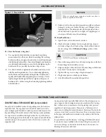
BAFFLES & LINERS
Sections
Liner
Liner Length Baffles
4
O TYPE
4”
9”
5
N/R
N/R
12”
6
V TYPE
12”
15”
7
V TYPE
14”
NONE
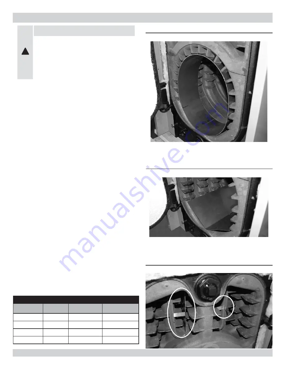
Figure 7 - Liner Baffle
Figure 8 - V-Shaped Baffle
Figure 9 - 3rd Pass Baffles


