background image

TI106 CDI Installation Manual 


20 June 2019


02179-00 


Issue AA 


______________________ 


Trig Avionics Europe B.V. 


Page 5


3.4.1


Wire Gauge Selection  

Wire gauge should be 24 AWG or thicker (smaller AWG; 22, 20, etc.). Use of PTFE, ETFE, TFE, Teflon, or Tefzel 
insulated wire is recommended for aircraft use per MIL-DTL-16878 or equivalent. Shielded twisted pair wiring per 
M27500 or equivalent is recommended for any signal wires which may be exposed to sources interfering with the 
integrity of the signal. 


Summary of Contents for TI106

Page 1: ...I106 Course Deviation Indicator Trig TI106 Course Deviation Indicator Installation Manual Installation Manual Installation Manual Installation Manual 02179 00 AA 20 June 2019 Trig Avionics Europe B V Hardwareweg 3 3821 BL Amersfoort Netherlands Copyright Trig Avionics Europe B V 2019 ...

Page 2: ...This page intentionally left blank ...

Page 3: ...pplied 4 3 2 2 Materials not supplied 4 3 3 EQUIPMENT LOCATION 4 3 4 CABLE HARNESS 4 3 4 1 Wire Gauge Selection 5 3 4 2 Interface Pinout 6 3 5 LIMITATIONS 7 3 6 REQUIREMENTS FOR TSO D VOR ILS SYSTEM 7 3 7 REQUIREMENTS FOR TSO D GLIDESLOPE SYSTEM 7 4 INSTALLATION 8 4 1 MOUNTING 8 4 2 INSTALLATION COMPLETION 8 5 OPERATION 10 5 1 PRE INSTALLATION TESTS 10 5 2 ANNUNCIATOR DIMMING ADJUSTMENT 10 5 3 OPE...

Page 4: ......

Page 5: ...aintenance procedures for the TI106 Course Deviation Indicator CDI 1 2 Scope This document applies to the Trig TI106 CDI 1 3 Changes from Previous Issue This is the first issue 1 4 Terms and Definitions BC Back Course CDI Course Deviation Indicator DC Direct Current DME Distance Measurement Equipment FAA Federal Aviation Administration GPS Global Positioning System ILS Instrument Landing System LE...

Page 6: ...ened or dimmed with an external lighting bus voltage for 5 14 or 28V systems Additionally the backlit LED annunciators are automatically adjusted for appropriate brightness using a built in photocell sensor which can be calibrated at the time of installation 2 2 Technical Specification Characteristics Parameter Specification Electrical Characteristics Input Voltage 12 32 VDC Input Current Maximum ...

Page 7: ...9 02179 00 Issue AA ______________________ Trig Avionics Europe B V Page 3 2 3 Qualification Specifications Qualification FAA TSO C34e C36e C40c EASA ETSO C34e C36e 2C40c Environmental Qualification RTCA DO 160B G Details listed in Appendix A ...

Page 8: ... that drive the CDI from other interference Avoid sharp bends in cabling and routing near aircraft control cables Also avoid proximity and contact with aircraft structures avionics equipment heat sources or other obstructions that could chafe or damage wires during flight and cause undesirable effects No direct cooling is required As with any electronic equipment overall reliability may be increas...

Page 9: ...Wire gauge should be 24 AWG or thicker smaller AWG 22 20 etc Use of PTFE ETFE TFE Teflon or Tefzel insulated wire is recommended for aircraft use per MIL DTL 16878 or equivalent Shielded twisted pair wiring per M27500 or equivalent is recommended for any signal wires which may be exposed to sources interfering with the integrity of the signal ...

Page 10: ...on Ref Input 9 To Input 10 From Input 11 Left Input 12 Right NAV Common Ref Input 13 Up Input 14 Down Glideslope Common Ref Input 15 Glideslope Valid Input 16 Glideslope Valid Glideslope Common Ref Input 17 GPS Annunciator Input 18 BC Annunciator Input 19 12 32 VDC Or pin 20 Input 20 12 32 VDC Or pin 19 Input 21 Power Ground Input 22 28V Lighting Input 23 14V Lighting Input 24 NAV Annunciator Inpu...

Page 11: ...ndards specification of the TI106 CDI and deviations listed below TSO devices must have separate approval for installation in an aircraft The TI106 CDI may be installed only according to 14 CFR Part 43 or the applicable airworthiness requirements 3 6 Requirements for TSO d VOR ILS System For a TSO d VOR ILS system the navigation receiver shall be certified to FAA TSO C40a b c or TSO C36c d e or la...

Page 12: ... within the aircraft in accordance with the aircraft manufacturer s instructions and the following steps 1 Verify that the instrument panel cut out meets the requirements of Figure 2 2 Secure the indicator to the instrument panel using the proper mounting hardware 3 Connect the electrical connector s to the connector on the back of the unit Figure 2 Panel Cut out Inches 4 2 Installation Completion...

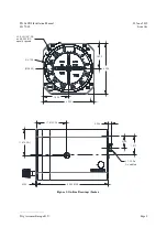
Page 13: ... Issue AA ______________________ Trig Avionics Europe B V Page 9 3 250 3 250 1 625 Ø3 120 Ø2 800 1 625 3X 6 32 UNC 2B on Ø3 500 B C equally spaced 1 910 CG 1 670 CG 0 125 4 584 MAX 1 217 0 765 0 206 J1 25 Pin D sub Male Figure 3 Outline Drawings Inches ...

Page 14: ...cept the OBS knob is first rotated to cause a FR From annunciator to be active lit To intercept a selected VOR radial from the station and fly outbound turn the OBS control to set the desired radial under the top indicator index Manoeuvre the aircraft to fly the selected radial magnetic heading plus 45 intercept angle which will provide a sufficient intercept angle The intercept angle should be re...

Page 15: ...er deflects upward the aircraft is below the glide path and the pilot must climb to intercept the glide path and centre the pointer If the pointer deflects downward the aircraft is above the glide path and the pilot must descend to intercept the glide path and centre the pointer When the pointer is centred the aircraft is on the glide path ...

Page 16: ... Trig Avionics Europe B V 6 Continued Airworthiness 6 1 Maintenance There is no scheduled maintenance required for the TI106 CDI If the unit fails to perform within operational specifications the unit must be removed and serviced by Trig Avionics The TI106 contains no field replaceable parts ...

Page 17: ... Trig Avionics Limited Trig Avionics Europe B V Heriot Watt Research Park Hardwareweg 3 Riccarton Edinburgh EH14 4AP 3821 BL Amersfoort Netherlands Trig Avionics will not accept or pay for any charges for warranty work performed outside our factory without prior written consent This warranty applies only to products in normal use It does not apply to units or circuit boards defective due to improp...

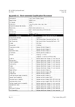
Page 18: ...ment identified as Category X no test required Waterproofness 10 Equipment identified as Category X no test required Fluids Susceptibility 11 Equipment identified as Category X no test required Sand and Dust 12 Equipment identified as Category X no test required Fungus 13 Equipment identified as Category X no test required Salt Spray 14 Equipment identified as Category X no test required Magnetic ...

Page 19: ...TI106 CDI Installation Manual 20 June 2019 02179 00 Issue AA ______________________ Trig Avionics Europe B V Page 15 ...

Reviews: