TN72 TABS GPS Receiver Installation Manual
5 January 2018
01691-00
Issue AG
______________________
Trig Avionics Limited
11
5.8.3
QMA Connector
This section describes the technique for attaching the antenna cable to the
supplied QMA connector.
The supplied connector can be completed using a wide range of commercial
crimp tools. The die apertures for the outer shield should be approximately 5.5
mm.
•
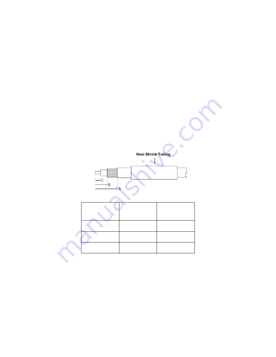
Strip back the coax cable to the dimensions in the table, as shown in
the diagram below. Slide 25 mm (1 inch) of heat shrink tubing over
the cable.
•
Slide the outer crimp sleeve over the cable – it must go on before
securing the centre contact.
Dimension
Cut size
(mm)
Cut size
(inches)
A
12
0.47
B
3.7
0.14
C
2
0.08
•
Solder the centre contact to the cable – heat contact using a dry
soldering iron, flow a small amount of solder into the bore hole of the
contact, insert cable and solder to contact. Clean contact and cable,
remove excess solder.
•
Insert the cable into the connector – the centre contact should click
into place in the body, the inner shield should be inside the body of the
connector and the outer shield should be outside the body.
Summary of Contents for TN72
Page 2: ...This page intentionally left blank ...
Page 31: ...This page intentionally left blank ...
Page 32: ......


