background image

TT21/TT22 Transponder Installation Manual 

22 August 2017 

00560-00 

AP 


______________________ 

40 

Trig Avionics Limited 


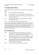
8.3  Mode Selector Knob 

The left hand knob controls the power to the transponder and the operating 
mode. 

OFF 

Power is removed from the transponder. 

SBY 

The transponder is on, but will not reply to any interrogations. 

GND 

The transponder will respond to Mode S ground interrogations from 
surface movement radar. 

ON 

The transponder will respond to all interrogations, but altitude 
reporting is suppressed. 

ALT 

The transponder will respond to all interrogations. 

When airborne, the transponder should always be set to ALT unless otherwise 
directed by Air Traffic Control.  When you are taxiing on the ground, the 
transponder should be set to GND unless your installation includes a gear squat 
switch or GPS based automatic Air/Ground determination which will 
automatically select GND on landing.  In these cases the mode switch can be 
left in ALT on the ground. 

8.4  Push Buttons 

IDT 

Press the IDT button when ATC instructs you to “Ident” or 
“Squawk Ident”.  This activates the SPI pulse in the transponder 
replies for 18 seconds.  IDT will appear in the display. 

FN 

Pressing the FN button provides access to changing the Flight ID 
and the ADS-B position monitor and display brightness control. 

VFR 

Pressing the VFR button sets the transponder to the pre-
programmed conspicuity code.  Pressing the button again 
restores the previous squawk code. 

ENT 

The ENT button enters a digit in the code selector. 

Summary of Contents for TT21

Page 1: ...TT21 TT22 Mode S Transponder Installation Manual 00560 00 AP 22 August 2017 Trig Avionics Limited Heriot Watt Research Park Riccarton Edinburgh EH14 4AP Scotland UK Copyright Trig Avionics Limited 2013 ...

Page 2: ...This page intentionally left blank ...

Page 3: ...22 DESCRIPTION 3 2 2 INTERFACES 3 2 2 1 TT21 TT22 Transponder Unit 3 2 2 2 TC20 Controller Unit 4 3 TECHNICAL SPECIFICATIONS 5 3 1 TT21 TRANSPONDER UNIT 00675 00 01 5 3 2 TT22 TRANSPONDER UNIT 00745 00 01 6 3 3 TC20 CONTROL UNIT 00649 00 7 3 4 INSTALLATION APPROVAL 8 4 UNIT AND ACCESSORIES SUPPLIED 9 4 1 TT21 MODE S TRANSPONDER ITEMS 9 4 2 TT22 MODE S TRANSPONDER ITEMS 9 4 3 TC20 CONTROLLER ITEMS ...

Page 4: ...T22 Interface Pinout 14 5 6 TT21 TT22 TRANSPONDER INTERFACE DETAILS 15 5 6 1 Power Input 15 5 6 2 TMAP Bus 16 5 6 3 Power On 16 5 6 4 Controller Power 16 5 6 5 Mutual Suppression 16 5 6 6 Ident Switch Input 17 5 6 7 Squat Switch Input 17 5 6 8 External Standby Input 17 5 6 9 GPS Position Input 17 5 6 10 TIS Traffic Output 18 5 7 TC20 CONTROLLER ELECTRICAL CONNECTIONS 18 5 7 1 TC20 Interface Pinout...

Page 5: ...ESSURE CONNECTION 27 6 INSTALLATION SETUP AND TEST 29 6 1 CONFIGURATION ITEMS 29 6 1 1 VFR Flight ID 29 6 1 2 Aircraft Address Programming 30 6 1 3 VFR Squawk Code 30 6 1 4 Airspeed Category 30 6 1 5 Aircraft Category 31 6 1 6 Squat Switch Source 31 6 1 7 TIS Output 31 6 1 8 GPS Input 31 6 1 9 GPS TIS Line Speed 31 6 1 10 GPS Certification Level 32 6 1 11 GPS NAC velocity 32 6 1 12 Aircraft Length...

Page 6: ...9 8 1 OVERVIEW 39 8 2 DISPLAY 39 8 3 MODE SELECTOR KNOB 40 8 4 PUSH BUTTONS 40 8 5 CODE SELECTOR KNOB 41 8 6 ALTITUDE ENCODER WARM UP 41 8 7 GENERAL LOW TEMPERATURE OPERATION 41 8 8 ADS B MONITOR 42 8 9 DISPLAY BRIGHTNESS CONTROL 42 8 10 WARNING MESSAGES 42 8 11 FAULT ANNUNCIATION 42 9 CONTINUED AIRWORTHINESS 44 10 LIMITED WARRANTY 45 11 ENVIRONMENTAL QUALIFICATION FORMS 46 12 ADS B COMPLIANCE 52 ...

Page 7: ...d v 12 3 CS ACNS COMPLIANCE 54 12 4 TSO C199 TABS COMPLIANCE 55 12 5 AUTOMATIC AIR GROUND DETERMINATION 55 12 6 ADS B SUPPORT 55 13 INSTALLATION DRAWINGS 56 13 1 MOUNTING TRAY FIXING AND OVERALL DIMENSIONS 56 13 2 FRONT PANEL CONTROLLER DIMENSIONS 57 13 3 FRONT PANEL CUT OUT OPTIONS 58 14 BASIC INTERCONNECT DIAGRAM 60 ...

Page 8: ...TT21 TT22 Transponder Installation Manual 22 August 2017 00560 00 AP ______________________ vi Trig Avionics Limited This page intentionally left blank ...

Page 9: ... version identifier for the TT21 and TT22 is 2 12 and the FPGA version identifier is 1 2 The TC20 controller software version identifier is 1 14 The software and FPGA versions are subject to change without notice 1 3 Changes from Previous Issue Changes from Issue AO to Issue AP are 5 6 7 Squat Switch Input Addition of note about GPS air ground determination 5 6 9 GPS Position Input Addition of Tri...

Page 10: ...TT21 TT22 Transponder Installation Manual 22 August 2017 00560 00 AP ______________________ 2 Trig Avionics Limited 1 4 Document Cross References 00559 00 TT21 Mode S Transponder Operating Manual AF ...

Page 11: ... The TT21 TT22 transponder is controlled using a separate front panel controller called the TC20 This allows the transponder to be mounted separately from the instrument panel and reduces the amount of panel space taken by the transponder The TC20 includes an altitude encoder The TC20 is certified to ETSO 2C112b and ETSO C88a and to FAA TSO C112c and TSO C88b The TT21 TT22 transponder runs from ei...

Page 12: ...tch Suppression bus I O ARINC compatible suppression bus signal used in aircraft with other pulse equipment such as DME This pin is both an input to and output from the transponder GPS Input Connection to a GPS supplying position input for ADS B position reporting TIS Output Connection to a traffic display 2 2 2 TC20 Controller Unit The TC20 controller has a single 9 way D type connector It provid...

Page 13: ...UROCAE ED 73C EUROCAE ED 14F RTCA DO 160F RTCA DO 181D RTCA DO 260B Software ED 12B RTCA DO 178B Level B Hardware DO 254 Level C Power Requirements 11 33 Volts DC Typical 5 Watts 14Volts Altitude 35 000 feet Humidity 95 50 C for 6 hours 85 38 C for 16 hours Tested to Category A in DO 160F Operating Temperature 20 C to 70 C Transmitter Frequency 1090MHz 1MHz Transmitter Power 125 Watts nominal 71 W...

Page 14: ... Class 1 Level 2els TSO C166b Class B1S FCC Identification VZI00745 Applicable documents EUROCAE ED 73C EUROCAE ED 14F RTCA DO 160F RTCA DO 181D RTCA DO 260B Software ED 12B RTCA DO 178B Level B Hardware DO 254 Level C Power Requirements 11 33 Volts DC Typical 6 Watts 14Volts Altitude 35 000 feet Humidity Tested to Category A in DO 160F Operating Temperature 20 C to 70 C Transmitter Frequency 1090...

Page 15: ...0 g 3 3 TC20 Control Unit 00649 00 Specification Characteristics Compliance ETSO 2C112b ETSO C88a TSO C112c TSO C88b Applicable documents EUROCAE ED 73B EUROCAE ED 14F RTCA DO 160F RTCA DO 181D SAE 8003 Software ED 12B RTCA DO 178B Level B Altitude 1000 to 35 000 feet Humidity 95 50 C for 6 hours 85 38 C for 16 hours Tested to Category A in DO 160F Operating Temperature 20 C to 55 C Physical Speci...

Page 16: ...ansponder are minimum performance standards It is the responsibility of those desiring to install this transponder on or within a specific type or class of aircraft to determine that the aircraft operating conditions are within the TSO standards The transponder may be installed only if further evaluation by the user installer documents an acceptable installation that is approved by the appropriate...

Page 17: ...675 00 01 TT21 TT22 Mounting Tray 1 00667 00 4 2 TT22 Mode S Transponder Items The TT22 Mode S transponder includes the following items Unit Description Qty Part Number TT22 Mode S Transponder 1 00745 00 01 TT21 TT22 Mounting Tray 1 00667 00 4 3 TC20 Controller Items The TC20 controller includes the following items Unit Description Qty Part Number TC20 Transponder Controller 1 00649 00 TT21 TT22 I...

Page 18: ...t housing female 1 00727 00 25 way D type contact housing male 1 00728 00 Crimp Terminal Male 22 24 AWG 20 00729 00 Crimp Terminal Female 22 24 AWG 9 00730 00 Static tubing EPDM 5mm ID 1 00731 00 Hose T piece 1 00732 00 Hose Adapter 2 00733 00 Hose clip small 6 00734 00 Hose clip large 2 00735 00 Long mounting screws 4 40 thread 4 00736 00 Short mounting screws 4 40 thread 4 00737 00 4 5 Required ...

Page 19: ...ings To secure the transponder tray to the airframe you will need at least 3 flat head screws and three self locking nuts If the aircraft does not have existing mounting provisions you may need to fabricate additional brackets to support the transponder tray To support the optional ADS B features a GPS receiver with an appropriate serial output is required To support the optional TIS features a di...

Page 20: ... connectors Select a position in the panel that is not too close to any high external heat source The TC20 is not a significant heat source itself and does not need to be kept away from other devices for this reason Avoid sharp bends and placing the cables too near to the aircraft control cables If you are using a 57mm instrument cut out you must first clip the two mounting adapters to the transpo...

Page 21: ... TT21 TT22 is not a significant heat source itself and does not need to be kept away from other devices for this reason Avoid sharp bends and placing the cables too near to the aircraft control cables Secure the mounting tray p n 00667 00 to the aircraft via the three 3 mounting holes in the tray The tray should be mounted to a flat surface it is important that the tray is supported at the dimples...

Page 22: ...ctrical Connections The TT21 TT22 has a single 25 way female socket which provides the data and power inputs to the transponder A single TNC coaxial connector attaches to the antenna 5 5 1 TT21 TT22 Interface Pinout Pin Signal Direction 1 Ground 2 TMAP1A Bidirectional 3 TMAP1B Bidirectional 4 Ground 5 GPS Position In Input 6 Ground 7 TIS Traffic Out Output 8 TMAP2A Bidirectional 9 TMAP2B Bidirecti...

Page 23: ...e 5 6 TT21 TT22 Transponder Interface Details 5 6 1 Power Input The power supply can be 11 33 Volts DC no voltage adjustment is required Use a 3 Amp circuit breaker for power supply protection to the TT21 TT22 It is always good practice to use more than one ground wire in an installation This is particularly important when the transponder is mounted on a non conducting surface such as a composite ...

Page 24: ...Power On The TT21 TT22 power supply can be directly controlled by this discrete input The input is active low so that the TT21 TT22 will power up whenever the input is held low This signal is intended to connect to the TC20 Remote ON output 5 6 4 Controller Power The TC20 controller does not connect to aircraft power it receives power from the TT21 TT22 using this output The TT21 TT22 provides 6 5...

Page 25: ...he input will be asserted when the voltage to ground is pulled below approximately 4 Volts The logical sense of the input can be programmed to be either active low or active high On an aircraft with no appropriate squat switch circuit this input should be left unconnected and the transponder programmed to ignore the input Note On an aircraft without a squat switch but configured for ADS B Out the ...

Page 26: ... B message depending on the intended airspace regulations For further information refer to Section 12 ADS B Compliance of this manual 5 6 10 TIS Traffic Output The TIS traffic is an RS232 output and supports the display of uplinked Traffic Information Service messages The TT21 TT22 TIS output can drive the Trig proprietary traffic protocol and can also support the format used by certain Garmin han...

Page 27: ...ut 6 Ground 7 Remote ON Output 8 Power Input 9 Ground The following diagram shows the connector orientation as viewed from the wiring side 5 8 TC20 Controller Interface Details 5 8 1 TMAP Bus TMAP is a Trig proprietary bus based on RS485 signalling It provides a bi directional interface between the transponder and the control head Each TMAP interface comprises a balanced pair of signals called A a...

Page 28: ...s input should NOT be connected to aircraft power 5 9 D Connector Crimp Terminals The 25 way and 9 way connectors supplied with the TT21 TT22 installation kit are MIL standard versions of the popular sub miniature D type connector family and use individual crimp terminals and a receptacle The MIL specification for this family of connectors is MIL C 24308 We supply crimp terminals because these are...

Page 29: ...ush the contact in until the retaining tab clicks into place Tug gently to confirm the contact is locked in place 5 10 Wiring Considerations The connection from the TT21 TT22 transponder to the TC20 uses a minimum of six 6 signal lines the TMAP pair the Power and Ground pair and the Remote On discrete line plus associated ground line In a certified installation the normal wire choice would be Tefz...

Page 30: ... with 6 or more cores is often more expensive than the individual wires and therefore is not generally a good choice for a certified aircraft For aircraft where those considerations do not apply however an attractive alternative solution may be to use 3 pair or 4 pair data cable Whilst appropriate cables may exist please note that not all data cable is suitable for this application Cables with sol...

Page 31: ...antenna is used it relies on a ground plane for correct behaviour For ideal performance the ground plane should be large compared to the wavelength of the transmission which is 275mm In a metal skinned aircraft this is usually easy to accomplish but is more difficult in a composite or fabric skinned aircraft In these cases a metallic ground plane should be fabricated and fitted under the antenna T...

Page 32: ...length is known a cable type with low enough loss per metre that meets the above requirements can be chosen Longer runs require lower loss cable Consider moving the TT21 TT22 closer to the antenna to minimise the losses in the antenna cable subject to the limits identified above the TT21 TT22 can be at any distance from the control head without affecting performance in any way Note Low loss cable ...

Page 33: ...42 21 1 0 23 311501 6 81 22 4 0 22 Aircell 7 8 22 26 11 0 18 311201 12 59 41 3 0 12 310801 Contact Electronic Cable Specialists on 1 414 421 5300 or at www ecsdirect com for their data sheets Contact SSB Electronic GmbH on 49 2371 95900 or at www ssb de for their data sheets When routing the cable ensure that you Route the cable away from sources of heat Route the cable away from potential interfe...

Page 34: ...it the supplied connector a short length up to 150mm or 6 inches of smaller cable may be used with suitable mating connectors to adapt to the transponder connector The supplied connector can be completed using a wide range of commercial crimp tools for example the Tyco 5 1814800 3 The die apertures for the inner pin and the outer shield should be approximately 1 72 mm and 5 41 mm respectively Stri...

Page 35: ... Static Pressure Connection The TC20 controller includes an altitude encoder which must be connected to the same source of static pressure as the primary altimeter on the aircraft The TC20 static pressure port provides a mounting spigot intended for nominal 5mm or 3 16 inch inside diameter tubing A length of 5mm EPDM rubber tubing is included in the installation kit to facilitate connection to the...

Page 36: ...nt although other combinations may be used For aircraft with inch static lines two adapters are provided which can convert from inch inside diameter hoses to the 5 mm hose in the install kit In all cases the static line should include drainage provisions and should be routed in accordance with CS 23 1325 or other applicable airworthiness provisions for the aircraft ...

Page 37: ...ollowing configuration items VFR Flight ID Registration Mode S Address VFR Squawk Code Aircraft Maximum Airspeed Aircraft Category Squat switch source if fitted TIS output format if used GPS position source if fitted and ADS B parameters This setup mode also allows the recalibration of the altitude encoder All the programming is accomplished using the right hand rotary knob and the ENT and FN butt...

Page 38: ...rt section of the Trig Avionics web site The Mode S address will be automatically populated if a valid USA registration has been entered at the previous step If the Mode S address is not already populated enter the 6 digit aircraft address using the rotary knob and the ENT button 6 1 3 VFR Squawk Code When the pilot presses the VFR button a pre programmed code will replace the current squawk code ...

Page 39: ...ight timer The sense of the squat switch input can be selected using the rotary knob If the squat switch input is not connected the Not Connected option must be selected 6 1 7 TIS Output If the aircraft has a Traffic Information Service TIS compatible display connected to the transponder select the appropriate interface protocol using the rotary knob Note TIS is a Mode S uplink service that is pro...

Page 40: ...rmation and is based on the certification standard that was used by the GPS vendor This will be indicated in the form of a letter code A to D on the data plate or installation documentation for the GPS in accordance with the standards DO 178B and DO 254 for example DO 178B level C If both standards are reported but at different levels use the lower standard higher letter This configuration item is...

Page 41: ...ADS B reported position Although primarily intended for position correction on large transport aircraft General Aviation aircraft can also have a significant offset For example if the aircraft has a long tail boom and the GPS antenna is on the top of the tail the GPS position could be 4 metres or more from the nose of the aircraft Enter the position of the GPs antenna relative to the nose of the a...

Page 42: ...ows you to adjust the built in altitude encoder to ensure that the altitude transmitted by the transponder corresponds to the altitude seen by the pilot on the primary altimeter This process is normally carried out every 24 months as part of the altimeter checks on the aircraft The maximum allowed difference between the primary altimeter and the altitude encoder is 125 feet in ETSO C88a and TSO C8...

Page 43: ...t sea level the first mid level point adjusts the correspondence around FL100 the second mid level point adjusts the correspondence at around FL200 and the high altitude point adjusts the correspondence at FL300 and above Since the altitude limit of the encoder is likely to be higher than the service ceiling of the aircraft it is sufficient to set only those adjustment points at or below the servi...

Page 44: ...nd turn the right knob on the TC20 until the altitude displayed on the TC20 matches the altitude on the primary altimeter 11 Press ENT on the TC20 the display moves to the MID ALTITUDE FL200 screen 12 If the service ceiling of the aircraft is below 20 000 feet the process is complete Press the ENT button twice more to get to the test screen Otherwise proceed to step 13 13 On the static test set dr...

Page 45: ...creen To complete the testing you should leave the TC20 screen displaying the encoder altitude and exercise the altitude on the static test set across the altitude range of the aircraft Use at least 10 test points and verify that in each case the altitude displayed on the primary altimeter and the altitude displayed on the TC20 correspond within the 125 foot tolerance Lightly tap the altimeter at ...

Page 46: ...mode should switch automatically to ALT Interrogations to verify the receiver sensitivity A Mode S transponder should have a minimum triggering level MTL of between 77 dBm and 71 dBm Failure to meet this requirement usually indicates antenna or coaxial cable problems Interrogations to verify the transmitted power A Class 1 installation should have no less than 125 Watts at the antenna and no more ...

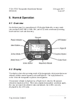
Page 47: ...used for code and data entry 8 2 Display The display shows the operating mode of the transponder the reported pressure altitude and the current squawk code and Flight ID The reply indicator is active when the transponder replies to interrogations The pressure altitude is displayed as a Flight Level which is the pressure altitude in hundreds of feet When non standard atmospheric conditions apply th...

Page 48: ...e directed by Air Traffic Control When you are taxiing on the ground the transponder should be set to GND unless your installation includes a gear squat switch or GPS based automatic Air Ground determination which will automatically select GND on landing In these cases the mode switch can be left in ALT on the ground 8 4 Push Buttons IDT Press the IDT button when ATC instructs you to Ident or Squa...

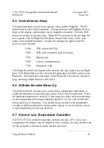
Page 49: ...l sign entered on your flight plan If no flight plan is active the aircraft registration should be used as your Flight ID Use only letters and digits If the Flight ID is less than 8 characters long entering a blank character will end it 8 6 Altitude Encoder Warm Up The built in altitude encoder uses a sensor that is temperature dependent A small internal heater circuit keeps the sensor at the corr...

Page 50: ...pear on the display with the title Brightness above the bar Rotate the Code Knob to select the desired brightness level Press FN to save the setting and return to the Squawk code display 8 10 Warning Messages If the transponder detects a problem the screen will indicate WARNING and a brief statement of the problem Depending on the nature of the problem your transponder may not be replying to inter...

Page 51: ...T21 TT22 Transponder Installation Manual 22 August 2017 00560 00 Issue AP ______________________ Trig Avionics Limited 43 on the screen and pass that information to your avionics maintenance organisation ...

Page 52: ...igned and manufactured to allow on condition maintenance This means that there are no periodic service requirements necessary to maintain continued airworthiness and no maintenance is required until the equipment does not properly perform its intended function When service is required a complete performance test should be accomplished following any repair action Repairs should only be carried out ...

Page 53: ...normal wear All warranties are F C A Trig Avionics Limited Heriot Watt Research Park Riccarton Currie EH14 4AP Trig Avionics will not accept or pay for any charges for warranty work performed outside our factory without prior written consent This warranty applies only to products in normal use It does not apply to units or circuit boards defective due to improper installation physical damage tampe...

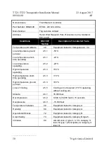
Page 54: ...w temperature ground survival 4 5 1 55 C Low temperature short time operating 4 5 1 40 C Low temperature operating 4 5 2 20 C High temperature operating 4 5 4 70 C High temperature short time operating 4 5 3 70 C High temperature ground survival 4 5 3 85 C Loss of Cooling 4 5 5 Cooling air not required 70 C operating without cooling air Altitude 4 6 1 35 000 feet Decompression 4 6 2 8 000 to 35 00...

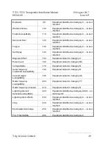
Page 55: ...X no test required Magnetic Effect 15 0 Equipment tested to Category Z Power Input 16 0 Equipment tested to Category BX Voltage Spike 17 0 Equipment tested to Category B Audio frequency conducted susceptibility 18 0 Equipment tested to Category B Induced signal susceptibility 19 0 Equipment tested to Category AC Radio frequency susceptibility 20 0 Equipment tested to Category TT Radio frequency em...

Page 56: ...rating 4 5 1 40 C Low temperature operating 4 5 2 20 C High temperature operating 4 5 4 70 C High temperature short time operating 4 5 3 70 C High temperature ground survival 4 5 3 85 C Loss of Cooling 4 5 5 Cooling air not required 70 C operating without cooling air Altitude 4 6 1 35 000 feet Decompression 4 6 2 8 000 to 35 000 feet in 15 seconds Overpressure 4 6 3 15 000 feet Temperature Variati...

Page 57: ...sted to Category Z Power Input 16 0 Equipment tested to Category BX Voltage Spike 17 0 Equipment tested to Category B Audio frequency conducted susceptibility 18 0 Equipment tested to Category B Induced signal susceptibility 19 0 Equipment tested to Category AC Radio frequency susceptibility 20 0 Equipment tested to Category TT Radio frequency emission 21 0 Equipment tested to Category B Lightning...

Page 58: ...rating 4 5 1 25 C Low temperature operating 4 5 2 20 C High temperature operating 4 5 3 55 C High temperature short time operating 4 5 3 70 C High temperature ground survival 4 5 3 85 C Loss of Cooling 4 5 5 Cooling air not required 70 C operating without cooling air Altitude 4 6 1 35 000 feet Decompression 4 6 2 8 000 to 35 000 feet in 15 seconds Overpressure 4 6 3 15 000 feet Temperature Variati...

Page 59: ... 0 Equipment identified as Category X no test required Voltage Spike 17 0 Equipment identified as Category X no test required Audio frequency conducted susceptibility 18 0 Equipment identified as Category X no test required Induced signal susceptibility 19 0 Equipment tested to Category BC Radio frequency susceptibility 20 0 Equipment tested to Category TT Radio frequency emission 21 0 Equipment t...

Page 60: ...lowing table summarises the ADS B parameters that are transmitted by the TT21 TT22 transponder when connected to an appropriate GPS receiver Parameter BDS Register SPI 0 5 Emergency Indicator 0 5 Barometric Altitude 0 5 Quality Indicator NIC 0 5 Airborne Position Latitude 0 5 Longitude 0 5 Quality Indicator NIC 0 6 Surface Position Latitude 0 6 Longitude 0 6 Surface Ground Speed 0 6 Surface Ground...

Page 61: ...PS system and the transmission time of the position data from the GPS to the transponder to determine the overall latency 12 2 FAA 91 227 Compliance The TT22 transponder is certified to TSO C166b and meets the requirements of AC 20 165B when directly connected to the GPS units listed below and will form the basis of a 14 CFR 91 227 compliant ADS B installation The following combinations are availa...

Page 62: ...e IFD 5xx ADS B Avi Trig ADSB Garmin GPS 20A n a Garmin ADSB For installations seeking certification to 91 227 or other applicable standards additional compliance information is available on request from Trig Avionics Limited 12 3 CS ACNS Compliance The TT21 or TT22 transponder can be connected to the following GPS units to form the basis of a CS ACNS compliant ADS B installation GPS Unit GPS Outp...

Page 63: ...ss Beacon System TABS is intended for voluntary equipage on aircraft exempted from carrying Automatic Dependent Surveillance Broadcast ADS B equipment such as gliders balloons and aircraft without electrical systems TABS devices provide interoperability with airborne and ground traffic receivers but do not meet the ADS B requirements defined in 14 CFR 91 227 12 5 Automatic Air Ground Determination...

Page 64: ... Transponder Installation Manual 22 August 2017 00560 00 AP ______________________ 56 Trig Avionics Limited 13 Installation Drawings 13 1 Mounting tray fixing and overall dimensions All dimensions in millimetres ...

Page 65: ...2 August 2017 00560 00 Issue AP ______________________ Trig Avionics Limited 57 13 2 Front Panel Controller Dimensions Controller shown without the mounting adapters 00678 00 used for 57mm 2 inch instrument mounting All dimensions in millimetres ...

Page 66: ...ed to either the compact mounting hole or a conventional 57mm 2 inch instrument cut out The compact mounting is a truncated 58 mm opening please note that the mounting screws are NOT in the same location for the two options Note The following diagram is intended to be to scale however variations in the printing process mean that you MUST check all dimensions before using it as a template ...

Page 67: ...560 00 Issue AP ______________________ Trig Avionics Limited 59 Note The following diagram is intended to be to scale however variations in the printing process mean that you MUST check all dimensions before using it as a template All dimensions in millimetres ...

Page 68: ...TT21 TT22 Transponder Installation Manual 22 August 2017 00560 00 Issue AP ______________________ Page 60 Trig Avionics Limited 14 Basic Interconnect Diagram ...

Page 69: ...Trig Avionics Limited This page intentionally left blank ...

Reviews: