TY96/96A and TY97/97A VHF Radio Installation Manual
26 September 2018
01238-00
Issue AJ
______________________
Page 12
Trig Avionics Limited
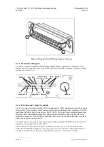
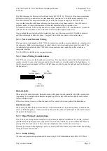
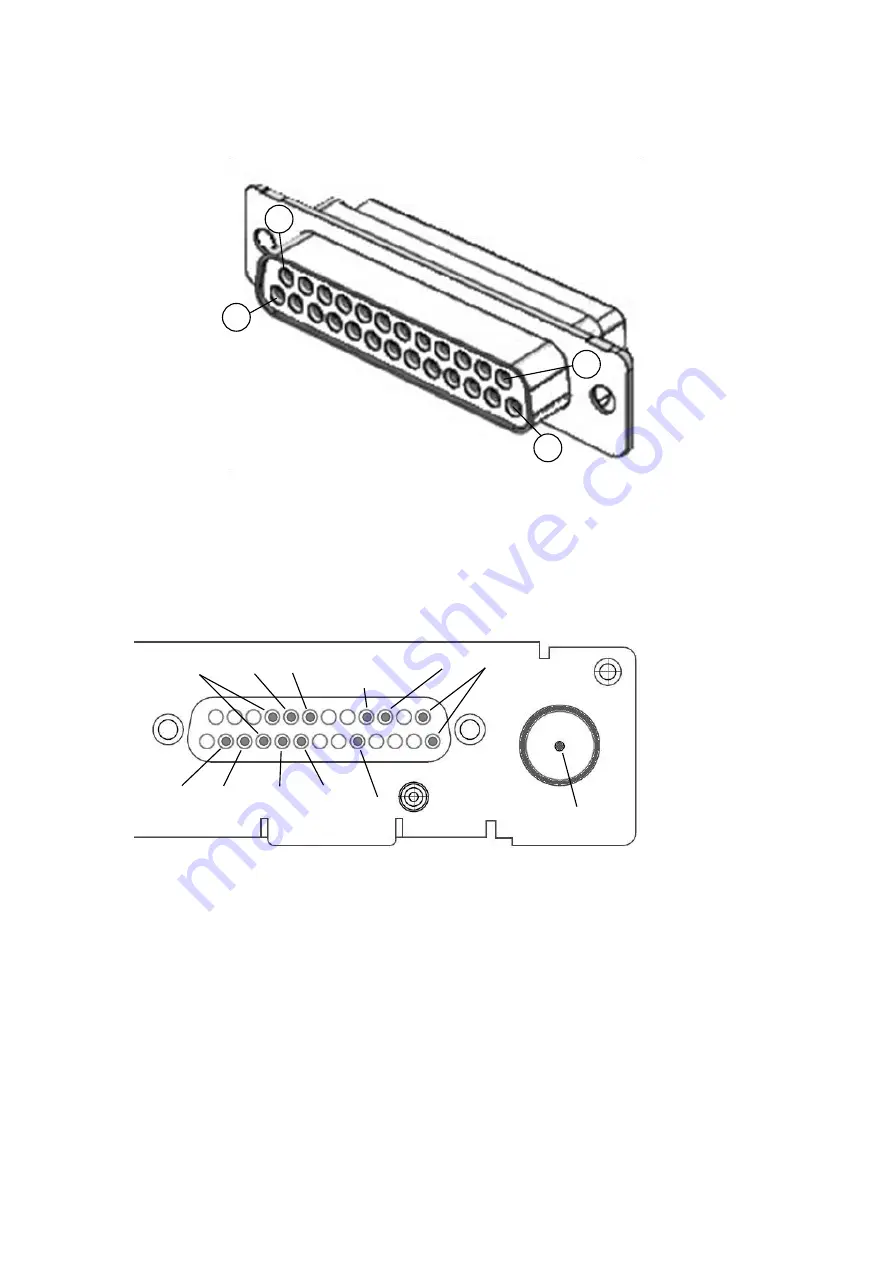
Figure 1: Mounting Tray 25 D-type Primary Connector
5.4.1
Orientation Diagram
To assist in connector orientation, the following example shows a typical set of connections. This
diagram shows the expected connector positions when viewed from the radio side of the tray, looking
into the tray from the front.
5.4.2
D Connector Crimp Terminals
The 25 way connector supplied with the TY96 installation kit are MIL standard versions of the popular
sub miniature D type connector family, and use individual crimp terminals and a receptacle. The MIL
specification for this family of connectors is MIL-C-24308. We supply crimp terminals because these
are more reliable than soldered connections, and are easier to assemble in-situ in an aircraft, where
soldering is impractical. They also allow individual wires to be removed and replaced in a receptacle
without replacing the whole connector.
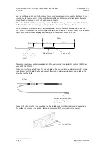
The socket contacts used in the connectors conform to MIL part number M39029/63-368, and are also
suitable for wire gauges from 20 to 24 AWG.
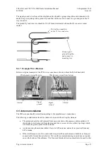
These contacts are widely used in avionics installation, and there are many tools available on the
market that will reliably crimp them to the wiring. Because the contacts are a MIL standard, there is
also a MIL standard for the crimp tool, although other proprietary solutions are available.
25
13
14
1
Power In
25
13
14
1
PTT
1
Intercom Key
enabled when connected to
ground
Mic
1
Mic
2
Ground
Left
Right
Headphone 1
Left
Right
Headphone 2 Ground
Antenna
Summary of Contents for TY96
Page 2: ...This page intentionally left blank ...
Page 6: ......


