20
PRELIMINARY: TR-FFT Fire Fighter’s Telephone Manual — LS10309-001TR-E:A 04/28/2021
Section 4: SLC Device Installation
4.1 List of SLC Devices
The following SLC devices can be used with the Fire Fighter’s Telephone. For more information, refer to the device installa-
tion instructions (packaged with the device).
4.2 Maximum Number of Devices
The TR-FFT supports up to 72 TR-MINIMON devices on one TR-FFT System.
4.3 Wiring Requirements for SLC Device
The information in Section 4.3 and Section 4.4 pertains to the TR-MINIMON - Mini Monitor Module.
4.3.1 Wiring SLC Devices in (Class B) Configuration
There is no special wire required for the addressable loops. The wire can be untwisted, unshielded, solid or stranded as long as
it complies with the National Electric Code 760-51 Requirements for Power-Limited Fire Protective Signaling Cables. Wire
distances are computed using copper wire.
•
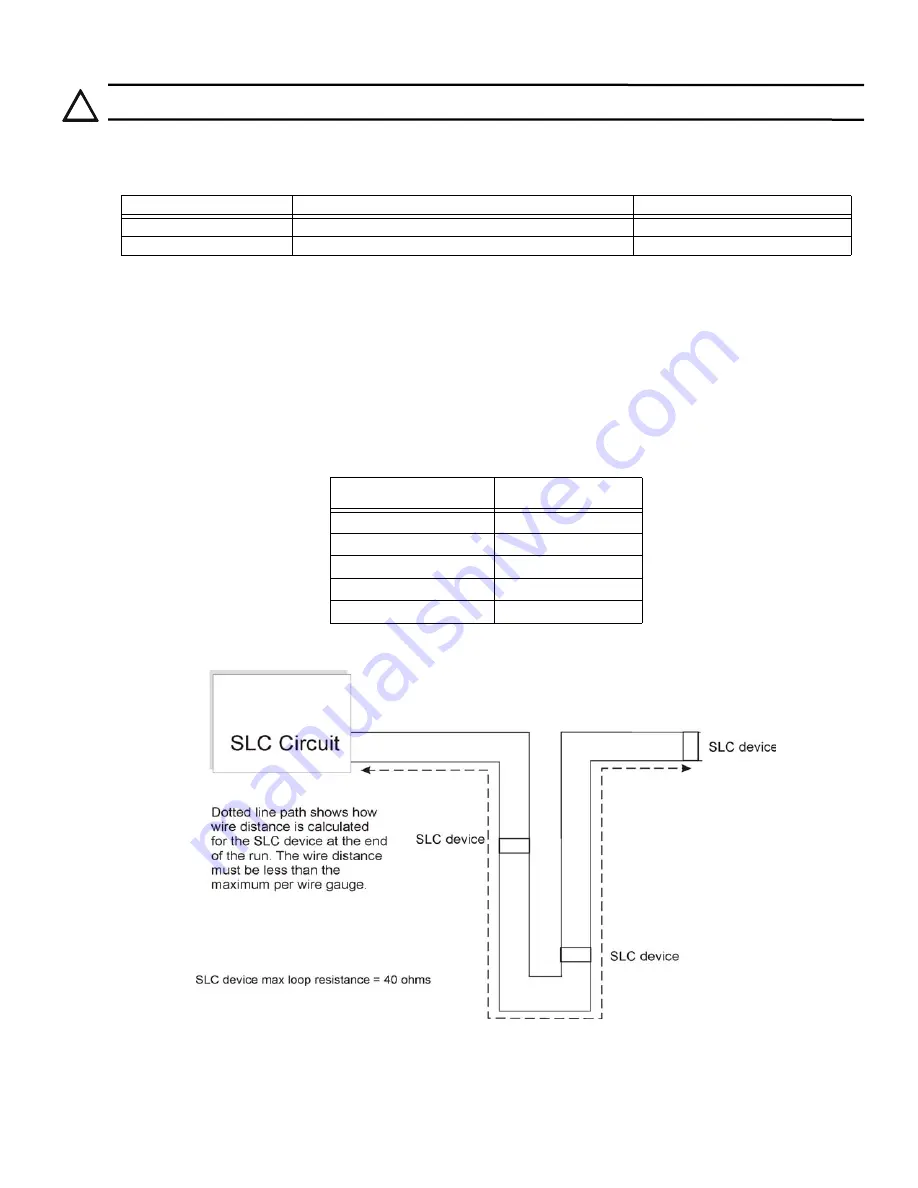
The maximum wiring resistance is 40 ohms to the farthest SLC device.
•
The maximum loop length depends on the wire gauge. See Table 4.2.
Figure 4.1 and Figure 4.2 show how the length is calculated when you use the Out and the Back Tap T-Tap style wiring.
.
Figure 4.1 Calculating the Wire Run Length for a Simple Out and Back
When you use the T-taps, the following are required:
•
The total length of all taps and the main bus must not exceed 40,000 feet.
•
Use the maximum distance requirements for the various wire gauges.
!
CAUTION: TO PREVENT THE RISK OF ELECTRICAL SHOCK AND DAMAGE TO THE UNIT, SHUT OFF THE POWER AT
THE CONTROL PANEL WHEN YOU INSTALL OR SERVICE THE CONTROL PANEL.
Device Part Number
Model Name/Description
Install Sheet Part Number
TR-MINIMON
Mini Monitor Module
I56-6978
TR-ISO
Fault Isolator Module
I56-6977
Table 4.1 SLC Devices
Wire Gauge
Max. Distance
22 AWG
1200 feet
18 AWG
3100 feet
16 AWG
4900 feet
14 AWG
7900 feet
12 AWG
10,000 feet
Table 4.2 Wiring Gauge and Distance Chart
Summary of Contents for TR-FFT
Page 33: ...Cut Along the Dotted Line ...


