PN LS10308-001TR-E:A 04/27/21 ECN: 151608
TR-STSR/TR-STSS Single Telephone Station
Product Installation Document
TRIGA Life Safety Systems, LLC
7600 Olde Eight Rd, Hudson, Ohio, 44236-1057
Tel: +1 330-577-5199, Email: info@trigaglobal.com
1 Description
The TR-STSR (recessed) and TR-STSS (surface mount) single Tele-
phone Stations are used with the TR-FFT Series Fire Fighter's Tele-
phone.
The TR-STSR/TR-STSS are compatible with the Triga Fire Fighters
Telephone TR-FFT Series. The Single Telephone Station Series has a
handset with a push-to-talk switch that is used for communication with
the main FFT controller or the other remote handsets.
1.1 Compatibility
The TR-STSR/TR-STSS is compatible with the Triga Series Fire Fighter
Telephone. For additional information, refer to the following Installation
Manuals.
2 Mounting Options
There are two options to mount the TR-STSR (recessed) and TR-STSS
(surface mount). Figure 3 shows the components of the Breakglass Kit.
Figure 3 Breakglass Kit
3 System Wiring
The following list the wiring specifications.
3.1 Telephone Wiring Connection
After the enclosure is mounted and the system wiring is completed,
assemble the telephones with the coiled cord handsets. To assemble the
telephones with the coiled cord handsets, refer to the following steps.
1.
Attach the system wiring to the terminal block on the telephone
chassis assembly.
2.
Insert the 6-32 nut in the backbox. Do not tighten the 6-32 nuts.
3.
Position and connect the telephone chassis assembly in the
backbox.
4.
To install the trim ring on the backbox, use the 6-32 wing nuts. Do
not tighten the 6-32 nuts.
5.
Position and install the door assembly. To secure the door assembly,
tighten the wing nuts.
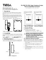
Figure 1 shows the single mount
telephone station.
Figure 1 Telephone Chassis
Figure 2 shows the backbox with
the mounting holes.
Figure 2
Backbox
Document
Document Part Number
TR-FFT Manual
LS10309-001TR-E
Tempered Glass
hammer
Figure 4 shows the TR-STSR
recessed-mount door with the
keylock.
Figure 4 TR-STSR Recessed-
Mount Door with Keylock
Figure 5 shows the TR-STSS
surface-mount door with the
keylock.
Figure 5 TR-STSS Surface-
Mount Door with Keylock
•
Riser Wiring Resistance (maximum)
50 ohms
•
Wiring Distance at 14AWG (maximum) 10,000 ft. (3048 m)
!
WARNING: THE SYSTEM WIRING FOR TELEPHONES
WITH COILED CORD HANDSETS MUST NOT BE
CONNECTED TO THE OUTSIDE WIRING. ALSO, DO
NOT RUN THE SAME CONDUIT OR CABLE TRAY AS
THE POWER OR CABLE TV LINES.
Recessed door
Surface-mount door


