


3
1.
GSM communicator
G09
GSM communicator
G09
is used to send security alarm system signals from the protected object to the IP
receivers operating in SIA standard DC-09 protocol in the monitoring station using GPRS.
Main features:
¾
messages are transmitted to the monitoring station via GPRS and/or via voice channel;
¾
messages transmitted using GPRS are sent in SIA standard DC-09 protocol and match protocol
Contact ID
codes;
¾
messages transmitted via voice channel may be sent to PSTN receiver in DTMF tones in SIA standard DC-05
protocol
Contact ID
codes;
¾
messages are sent via indicated communication channel or, if communication fails
–
via the backup channel;
¾
ability to send SMS messages to the mobile phones of up to 4 users;
¾
two NC type inputs;
¾
one PGM output, which may be controlled remotely;
¾
operation parameters are set using USB connection and software
G10config
;
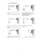
1.1.
Operation description
Communicator
G09
may be connected to security control panel data bus, its programmable outputs or to control
panel telephone communicator using adequate connection. Information is read, converted to corresponding
Connect ID
protocol codes and transmitted via communication channels set during the programming. Messages are sent to the
monitoring station and/or user mobile phones.
Communicator sends messages regarding status changes in the external circuit of inputs
IN1
and
IN2
. Message
transmission may be suspended temporarily by setting input
IN1
to control mode.
Communicator controls power supply and, in case of the limits being exceeded, generates and sends appropriate
messages and signals about it using light indicators.
Two technologies are supported for message transmission to the monitoring station: GPRS and/or voice channel
sending DTMF tones. SMS text messages are sent to users.
Messages are using GPRS technology in TCP/UDP protocols following SIA standard DC-09 requirements.
Received or generated message is sent via set main channel. Communicator sends messages to users once a
message reception confirmation is received from the monitoring station receiver. If confirmation is not received in time,
message transmission is repeated several times, and if unsuccessful, carried out via the backup channel (if such is set).
Messages may be sent to four user mobile phones using SMS messages. Every security panel message is attributed
with a understandable SMS text message. SMS messages may be distributed among the different users according to a
sent message type.
Communicator may perform a continuous communication control of receiving equipment by periodically sending
communication test signals, to which reception confirmation is being received. When communication via the main
channel fails (reception confirmation is not received), messages are being transmitted via the backup channel.
Communicator will periodically try to restore communication via the main channel according to the parameters set
during the programming.
Communicator output OUT1 status changes when facing communication or operation problems. Operation mode is
set during the programming.
Received or generated messages is directed to a MCI data bus. MCI data bus is designated for message transmission
via several different communication channels. MCI data bus messages are received only by compatible devices: SP131,
G10, E10, T10.
Communicator messages are received by the receiver in the monitoring station.
Messages sent via IP channels are received by an IP receiver which is able to receive and process messages sent in
standard SIA DC-09 protocol. Encrypted or not encrypted messages may be sent. Communicator also sends the
communication device identification number, which may match the object identification number or may be original.
Messages sent in DTMF signals are received by PSTN telephone receiver which is able to receive and process
messages sent in standard SIA DC-05 protocol.


