background image


www.trikdis.com  


  7   


January, 2021 


Cellular communicator G16T_LTE-M 
 

Terminal 

Description 

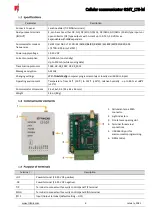
I/O 2  

Input/Output terminal (default setting 

 IN, NO circuit) 

I/O 3 

Input/Output terminal (default setting 

 Output)  

COM 

Common terminal (negative) 

A 485 

RS485

 bus A contact 

B 485 

RS485

 bus B contact  


Indicator 

Light status 

Description 

NETWORK 

Off 

No connection to cellular network  

Yellow blinking 

Connecting to cellular network 

Green solid with yellow 
blinking   

Communicator is connected to cellular network.  

Sufficient cellular signal strength for 4G level 3 (three yellow flashes) 

DATA 

Off 

No unsent events 

Green solid 

Unsent events are stored in buffer 

Green blinking 

(Configuration mode) 

Data is being transferred to/from communicator 

POWER 

Off 

Power supply is off or disconnected 

Green solid 

Power supply is on with sufficient voltage  

Yellow solid 

Power supply voltage is insufficient (≤11.5V)


Green solid and yellow 
blinking   

(Configuration mode) 

Communicator is ready for configuration 

Yellow solid 

(Configuration mode) 

No connection with computer  

TROUBLE 

OFF 

No operation problems  

1 red blink  

SIM card not found  

2 red blinks 

SIM card PIN code problem (incorrect PIN code)  

3 red blinks 

Programming problem (No APN)  

4 red blinks 

Registration to GSM network problem  

5 red blinks 

Registration to GPRS/UMTS network problem  

6 red blinks 

No connection with the receiver  

7 red blinks 

Lost connection with control panel  

Red blinking 

(Configuration mode) 

Memory fault  

Red solid 

(Configuration mode)

 Firmware is corrupted  

BAND 

1 green blink  

None  

5 green blinks 

LTE CAT_M1  

6 green blinks 

LTE TDD, LTE FDD  

Summary of Contents for G16T

Page 1: ...www trikdis lt UAB Trikdis Draugyst s str 17 LT 51229 Kaunas Lithuania 370 37 408 040 info trikdis lt Cellular communicator G16T Installation manual January 2021...

Page 2: ...TING IO 8 EXPANSION MODULE 13 3 7 SCHEMATIC FOR CONNECTING THE W485 WIFI MODULE 14 3 8 SCHEMATIC FOR CONNECTING THE E485 ETHERNET MODULE 14 3 9 TURN ON THE COMMUNICATOR 14 PROGRAMMING THE CONTROL PANE...

Page 3: ...d Approvals These listings and approvals apply only to the module specified in this document In some cases listing may be in process FCC Statement This equipment complies with FCC rules Part 15 FCC re...

Page 4: ...s malfunctions if the communicator is installed or used not according to its manual the communicator s malfunctions if the cause is a malfunction or loss of GSM GPRS Internet connectivity or malfuncti...

Page 5: ...09 receivers Connection supervision by polling to IP receiver every 30 seconds or by user defined period Backup channel that will be used if connection with the primary channel is lost With parallel...

Page 6: ...rotocols TRK8 DC 09_2007 DC 09_2012 Message encryption AES 128 Changing settings With TrikdisConfig computer program remotely or locally via USB Mini B port Operating environment Temperature from 14 F...

Page 7: ...ransferred to from communicator POWER Off Power supply is off or disconnected Green solid Power supply is on with sufficient voltage Yellow solid Power supply voltage is insufficient 11 5V Green solid...

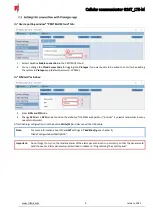
Page 8: ...with TrikdisConfig software 1 Download configuration software TrikdisConfig from www trikdis com type TrikdisConfig in the search field and install it 2 Open the casing of the G16T with a flat head sc...

Page 9: ...SIM card PIN code 4 Change APN name APN can be found on the website of the SIM card operator internet is universal and works in many operator networks After finishing configuration click the button Wr...

Page 10: ...for your event messages TRK8 to TRIKDIS receivers DC 09_2007 or DC 09_2012 to universal receivers 4 TRK encryption key enter the encryption key that is set in the receiver 5 Domain or IP enter the re...

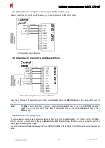
Page 11: ...et it up correctly so that the panel would send the events Alarm panel setup is described in chapter 4 Programming the control panel Installation and wiring 1 Remove the top cover and pull out the con...

Page 12: ...ls that can be set to an OUT PGM operating mode The outputs can control three areas of the security system Area control settings are made in the Protegus app The communicator has 3 universal input out...

Page 13: ...expander With relay contacts you can control turn on off various electronic appliances The I O terminal of the communicator must be set to an output OUT mode If more inputs or outputs need to be conn...

Page 14: ...nto the communicator G16T for E485 to work To start the communicator turn on the security control panel s power supply This LED indication on the G16T communicator must show POWER LED illuminates gree...

Page 15: ...must be set to 5 50 delay for sending burglary alarm events optional Default value is 2 0 With it the event message transmission will be delayed for 30 seconds If you want the message to be sent imme...

Page 16: ...and the packaging sticker After entering press Next Important The control panel zone to which the G16T output OUT is connected to has to be set to keyswitch mode Follow the instructions below if the s...

Page 17: ...h zone You can also change the duration of the pulse interval if it is required for the connected control panel 5 For additional security you can select Use Application password for ARM DISARM Then af...

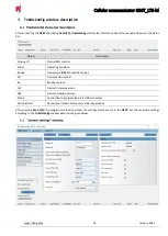
Page 18: ...number Status Operating condition Device Device type G16T should be shown SN Device serial number BL Browser version FW Device firmware version HW Device hardware version Status Connection to program...

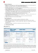
Page 19: ...Fourth HSK tone handshake control panel tone It is recommended to leave the default settings Dial tone frequency frequency in which the G16T communicates with the control panel landline dialer Time s...

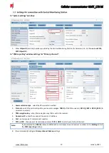
Page 20: ...bed above Settings tab Settings settings group Test period TEST event period for testing the connection Test events are sent as Contact ID messages and forwarded to the monitoring software IP ping per...

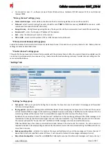
Page 21: ...ection will be used for sending events via IP channel to the monitoring station receiver or to Protegus ensure that mobile data service is enabled SIM card settings group SIM card PIN enter the SIM ca...

Page 22: ...or Restore CID enter the event code or leave the default value Upon entering the event the event code will be sent to Protegus and CMS SIA enter the event code or leave the default value Upon enterin...

Page 23: ...on receiver and to Protegus app Contact ID event code Enable allow message transmission when the input is triggered E R choose what type of event will be sent when input is triggered Event or Restore...

Page 24: ...Fi network password In the table you can assign Contact ID SIA 4 2 event and restore codes to the RS485 data bus fault event When connection between the W485 and G16T is disrupted or re established th...

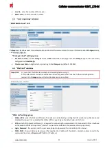
Page 25: ...vent messages sent by the device After turning off an internal event in this window it will not be sent irrespective of other settings COMMUNICATION message about connection error between the control...

Page 26: ...trigger them and make sure you receive the correct event 4 To test the communicator outputs activate them remotely and check their operation 5 If the security control panel will be controlled remotely...

Page 27: ...www trikdis com 27 January 2021 Cellular communicator G16T_LTE M 6 Wait for the update to complete...

Reviews: