
www.trikdis.com
4
December, 2022
iO-8-LORA Wireless Expander
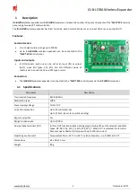
1
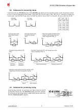
Description
iO-8-LORA
wireless expanders with
RF-LORA
transceiver increase the number of inputs and outputs of the
"FLEXi" SP3
security
panel using two-way RF communication.
The
iO-8-LORA
wireless expander has 8 I/O terminals, each of which can be set as an input (IN) or as an output (OUT).
Features
Communication:
Line-of-sight wireless range up to 1000 m.
Up to 8
iO-8-LORA
wireless expanders can be connected to the
"FLEXi" SP3
control panel.
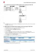
Inputs and outputs:
8 I/O terminals, each one can be set as an input (IN) or output
(OUT). Input (IN) types: ATZ, EOL, NC, NO. Different value of
resistors can be used in EOL and ATZ type circuits.
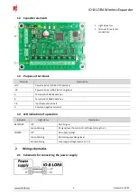
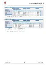
Connection:
The
iO-8-LORA
wireless expander is connected to the
"FLEXi" SP3
control panel via the
RF-LORA
transceiver
.
1.1
Specifications
Parameter
Description
Transmission frequency
867-869 MHz
Modulation type
LORA
Power supply voltage
10-26 V DC
Current consumption
Up to 50 mA (stand-by)
Up to 120 mA (short-term, while sending)
Report encryption
Yes
Range in open space
Up to 1000 m
Dual purpose terminals [I/O]
8, IN or OUT function selected during programming. When IN is selected, available
types: NC, NO, EOL, EOL_T, 3EOL, ATZ, ATZ_T. When OUT is selected, the terminal
becomes open collector (OC) type with up to 100 mA current
Operating environment
Temperature from –20 °C to +50 °C, relative humidity – up to 80% at +20 °C
Dimensions
65 x 90 x 12 mm
Weight
80 g


